Wheel-shaft type energy saving beam-pumping unit

A technology of pumping units and beams, which is applied in the field of axle-type energy-saving beam pumping units, can solve the problems of potential safety hazards, high operating costs, and high management costs, and achieve improved utilization effects, reduced labor intensity, and reduced energy consumption Effect

Active Publication Date: 2020-02-07
山东博康石油工程技术有限公司
View PDF5 Cites 4 Cited by
  • Summary
  • Abstract
  • Description
  • Claims
  • Application Information

AI Technical Summary

Problems solved by technology

[0006] In order to solve the problems of high initial investment cost, high management cost, high operating cost and potential safety hazards of existing pumping units, the present invention aims to propose a wheel-shaft energy-saving beam pumping unit

Method used


Image

  • Wheel-shaft type energy saving beam-pumping unit
  • Wheel-shaft type energy saving beam-pumping unit
  • Wheel-shaft type energy saving beam-pumping unit

Examples


Embodiment Construction

[0025] The present invention will be further described below in conjunction with accompanying drawing:

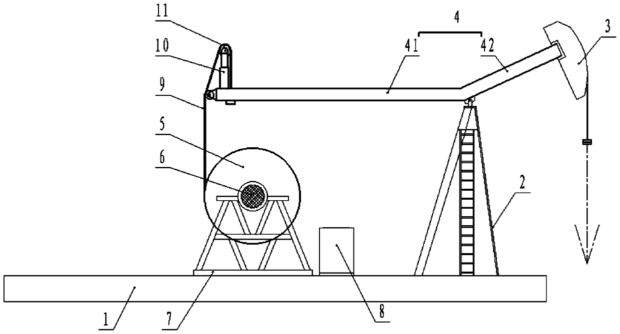
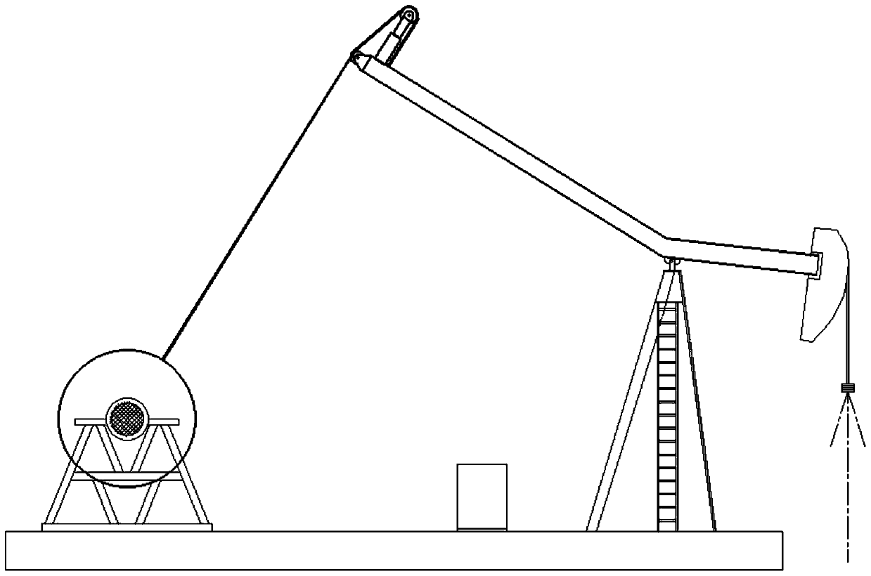
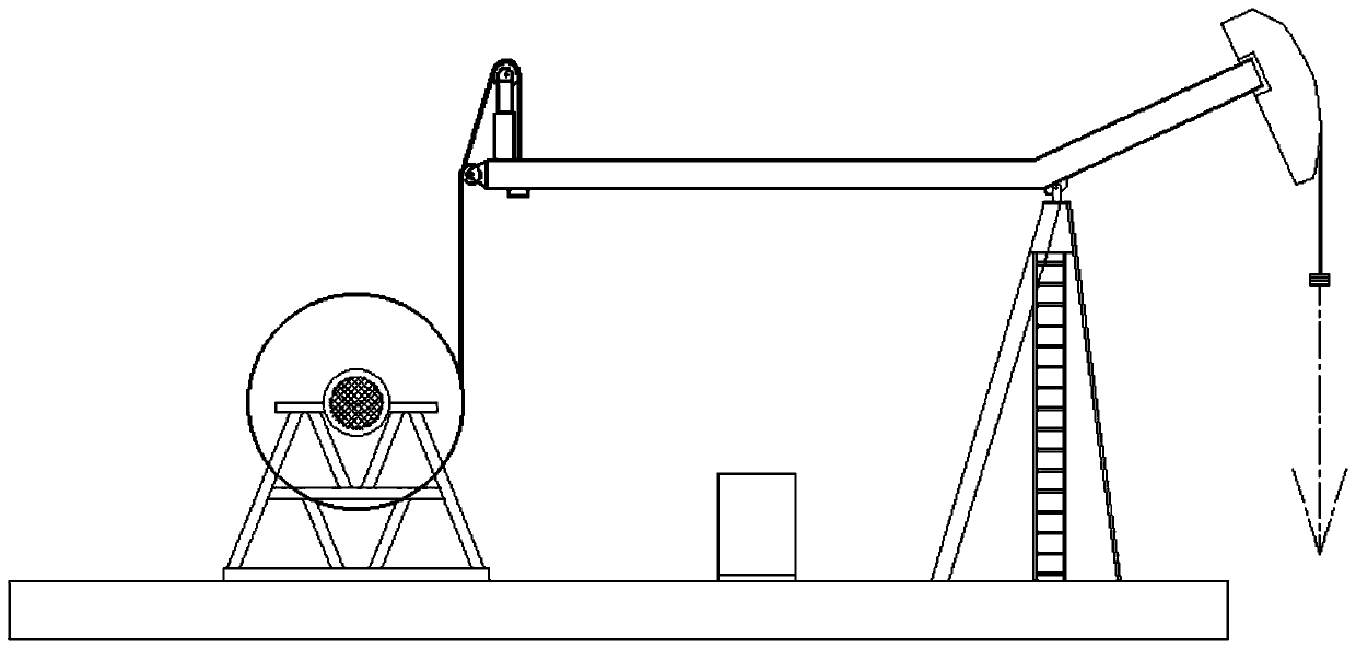
[0026] combined with Figure 1-6 , a wheel-shaft energy-saving beam pumping unit in this embodiment, comprising a base 1, a bracket 2, a donkey head 3, a beam 4 and a driving device, the bracket 2 is fixed on the base 1, and the beam 4 is hinged on the top of the bracket 2 , The donkey head 3 is installed on one end of the beam 4, and the other end of the beam 4 is connected with the driving device. The above are existing structures in the prior art, and will not be repeated here.

[0027] The innovation point of the present invention is:

[0028] The beam 4 includes two straight sections at an obtuse angle, which are respectively called the long section beam 41 and the short section beam 42 according to different lengths. On the premise of ensuring the stroke of the pumping unit, increasing the length of the long section beam 41 is reflected in the principle of leverage...


PUM


Abstract

The invention relates to the technical field of artificial lift oil recovery methods of oil fields, in particular to a wheel-shaft type energy saving beam-pumping unit. The wheel-shaft type energy saving beam-pumping unit includes a base, a bracket, a horsehead, a walking beam and a driving device, the walking beam includes two straight sections at obtuse angles, the driving device includes a roller, a motor, a frequency conversion control cabinet and an installation seat, the motor directly drives the roller to rotate, one end of a long section walking beam is connected with a wire rope, theother end of the wire rope is wound around the roller, the base is embedded with a cylindrical double guide rail, the lower part of the installation seat is a double sliding sleeve, and the double sliding sleeve sleeves the cylindrical double guide rail and can slide axially relative to the cylindrical double guide rail. Compared with the prior art, the wheel-shaft type energy saving beam-pumpingunit omits a reduction gearbox, a belt, a crank connecting rod mechanism and other parts prone to mechanical failure, the pumping unit sequential input cost, the management cost and the operating costare lowered, and the good energy saving effect is achieved.

Description

technical field [0001] The invention relates to the technical field of oil field artificial lifting oil recovery method, in particular to a wheel shaft type energy-saving beam pumping unit. Background technique [0002] In the present artificial lift production method, beam pumping units account for more than 90%. Judging from years of operation, the current beam pumping unit has the following problems: [0003] 1. High initial investment cost: In addition to the necessary facilities such as beams and motors, some auxiliary facilities such as gearboxes, cranks, balance weights, and belts are also essential, which increases the input cost. [0004] 2. High management cost: During the operation process, it is necessary to change the belt frequently, adjust the balance weight weighing several thousand kilograms, maintain the gearbox, etc., which increases the labor intensity of workers and management costs. [0005] 3. High operating cost: The downstroke cannot fully utilize ...

Claims


Application Information

Patent Timeline
Patent Type & Authority Applications(China)
IPC IPC(8): E21B43/00
CPCE21B43/127
Inventor 不公告发明人
Owner 山东博康石油工程技术有限公司
Why Eureka
Try Eureka