Waveguide type liquid crystal-based laser scanning control method
A technology of laser scanning and control method, applied in the fields of microelectronics and optics, to achieve the effect of reducing the amount of calculation, reducing the response time, and simplifying the calculation
- Summary
- Abstract
- Description
- Claims
- Application Information
AI Technical Summary
Problems solved by technology
Method used
Image
Examples
Embodiment 1
[0050] Example 1:
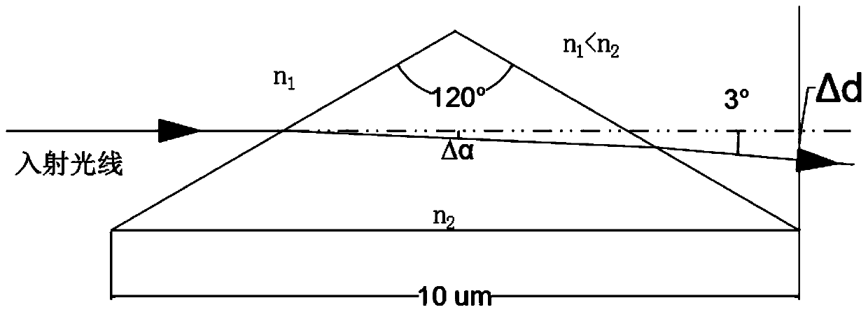
[0051] Such as figure 1 , This is an enlarged view of the laser angle control unit. Take the isosceles triangle laser angle control unit with an apex angle of 120° as an example. The laser angle control unit is set as a waveguide liquid crystal with a refractive index of n 2 , The refractive index setting of other non-working area S n 1 , When a voltage is applied to the laser angle control part, due to the characteristics of the waveguide liquid crystal, the refractive index becomes larger, n 2 > n 1 , So the incident light can be deflected by 3°. The bottom side length of the controller is set to 10μm. Of course, in other embodiments, the top angle and bottom side length can be adaptively changed to achieve the same technical effect, or other areas can be directly powered on to achieve negative Voltage light angle control.
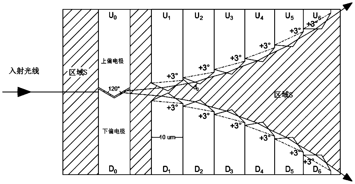
[0052] Such as figure 2 The laser angle control unit is used to form a laser scanning control structure based on waveguide liquid crysta...
Embodiment 2
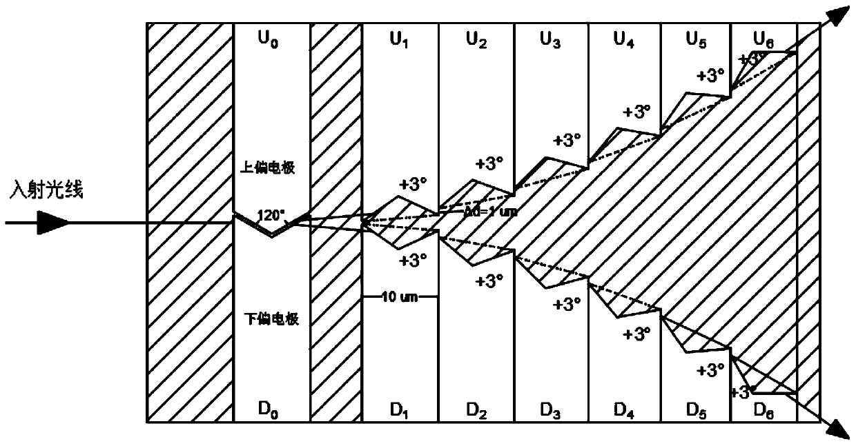
[0056] Such as figure 2 In the second embodiment, on the basis of the first embodiment, the upper and lower deflection electrodes are arranged symmetrically along the incident direction of the light. In this way, it is easier to calculate the angle after the deflection, and the angle after the deflection is easier to calculate. In example 2, the light angle control part of each electrode is set to the same isosceles triangle or isosceles trapezoid, as in figure 2 It is set to a light angle control structure that can deflect the light by 3°, so that each light deflection is set to the same angle, that is, the same electrodes are cascaded, which is very easy to calculate. Because the waveguide type liquid crystal receives the electrode signal, There is a non-linear refractive index change, so for the waveguide type liquid crystal, if the angle is set to the same angle, the angle change and period can be calculated relatively easily.
Embodiment 3
[0058] In Embodiment 3, different electrodes can also be set to different angles of deflection. For example, a large-angle deflection is the main method and a small-angle deflection is a supplementary method. For example, the front deflection angle is set to 5° deflection, and the small electrode at the back It is set to 3° deflection, and the deflection angle at the extreme edge is set to 2° or 1° deflection. Of course, different angles can also be used in other embodiments. In this way, it is better than setting the deflection of each light to the same angle. This can be calculated The angle of the pseudo-deflection can be further adjusted by choosing different electrodes, but this is more computationally expensive.
PUM
 Abstract
Description
Claims
Application Information
 - R&D
- Intellectual Property
- Life Sciences
- Materials
- Tech Scout
- Unparalleled Data Quality
- Higher Quality Content
- 60% Fewer Hallucinations
Browse by: Latest US Patents, China's latest patents, Technical Efficacy Thesaurus, Application Domain, Technology Topic, Popular Technical Reports.
© 2025 PatSnap. All rights reserved.Legal|Privacy policy|Modern Slavery Act Transparency Statement|Sitemap|About US| Contact US: help@patsnap.com


