Method for controlling forged blade extrusion molding residual stress

A residual stress, extrusion forming technology, applied in the direction of manufacturing tools, forging/pressing/hammer devices, forging/pressing/hammering machinery, etc. rate effect

Active Publication Date: 2020-02-11
CHINA HANGFA SOUTH IND CO LTD
View PDF9 Cites 2 Cited by
  • Summary
  • Abstract
  • Description
  • Claims
  • Application Information

AI Technical Summary

Problems solved by technology

However, on the one hand, these solutions have high energy consumption, and on the other hand, the process is more complicated, so the manufacturing cost will be greatly increased.

Method used


Image

  • Method for controlling forged blade extrusion molding residual stress
  • Method for controlling forged blade extrusion molding residual stress
  • Method for controlling forged blade extrusion molding residual stress

Examples


Embodiment Construction

[0036]In order to have a clearer understanding of the technical features, purposes and effects of the present invention, the specific implementation manners of the present invention will now be described with reference to the accompanying drawings. Wherein, the same parts adopt the same reference numerals.

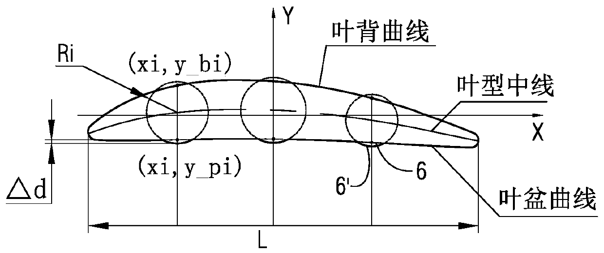
[0037] As mentioned in the background art, the existing high-speed extrusion molding process has the disadvantages of large residual stress and easy bending deformation of the blade. The inventor has carried out in-depth calculation and analysis on its principle, see figure 2 As shown, in the cavity of the blade body part formed by the blade pot mold 11 and the blade back mold 12, since the contour line of the blade back is longer than the contour line of the blade pot, when the blade blank is extruded at a high speed , the surface area of ​​the metal in contact with the leaf back mold 12 is greater than the surface area in contact with the leaf basin mold 11, which easi...


PUM


Abstract

The invention discloses a method for controlling forged blade extrusion molding residual stress. The method comprises the following steps: (A) according to theoretical blade type data of blade parts,basic molded surfaces and parameters of corresponding characteristic sections of blade blanks are obtained; (B) new blade basin part curves are obtained on each characteristic section of the blade blanks obtained in the step (A); (C) continuous and complete molded surfaces and parameters of blade body parts of new blade blanks are obtained after molded surfaces and parameters of all characteristicsections of the new blade blanks are obtained in the step (B); and (D) new blade basin molds are designed according to the molded surfaces and the parameters of the new blade blanks obtained in the step (C) to manufacture the new blade blanks. The method for controlling forged blade extrusion molding residual stress can effectively control residual stress of the blades generated in a high-speed extrusion molding process to greatly improve the pass percent of the blade blanks.

Description

technical field [0001] The invention relates to the technical field of forging, in particular to a method for controlling the residual stress of forged blade extrusion forming when the forging process utilizes a high-speed extrusion forming process to manufacture blade blanks in the process of manufacturing aeroengine blades. Background technique [0002] The blade is one of the important parts of the aero-engine. For the blade, the accuracy of the surface size of the airfoil is very important. The compressor blade is located near the air inlet of the aero-engine. This type of blade is generally made of blade blank by forging forming process, and then enters the subsequent process for precision machining (including electrolysis, digital milling, polishing and other processing operations). [0003] figure 1 It is a schematic diagram of the process principle of high-speed extrusion of the blade; figure 2 for figure 1 The schematic diagram of the cross-sectional structure o...

Claims


Application Information

Patent Timeline
Patent Type & Authority Applications(China)
IPC IPC(8): B21K3/04B21J13/02
CPCB21J13/02B21K3/04
Inventor 朴学华江杨辉雷雪峰左华付李强秦婷婷
Owner CHINA HANGFA SOUTH IND CO LTD
Why Eureka
Try Eureka