An equidistant cutting device for construction wood processing
A technology of isometric cutting and wood, which is applied to wood processing appliances, manufacturing tools, forming/shaping machines, etc., to achieve the effects of simple and convenient operation, reduced number and simple structure.
- Summary
- Abstract
- Description
- Claims
- Application Information
AI Technical Summary
Problems solved by technology
Method used
Image
Examples
Embodiment 1
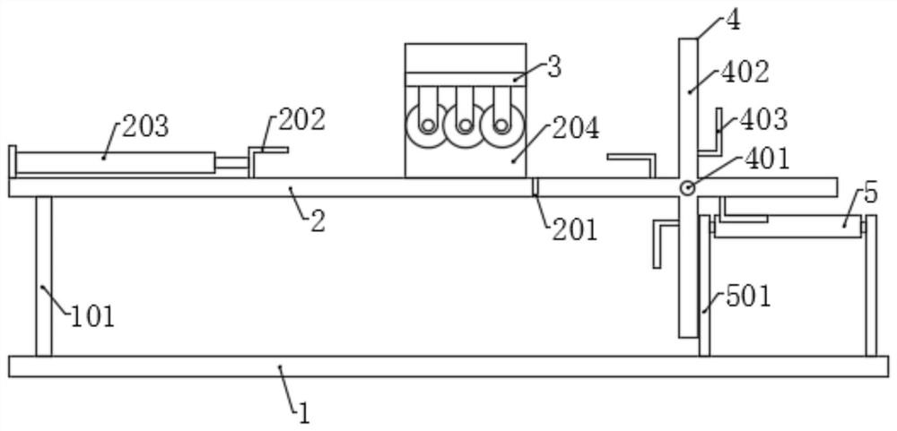
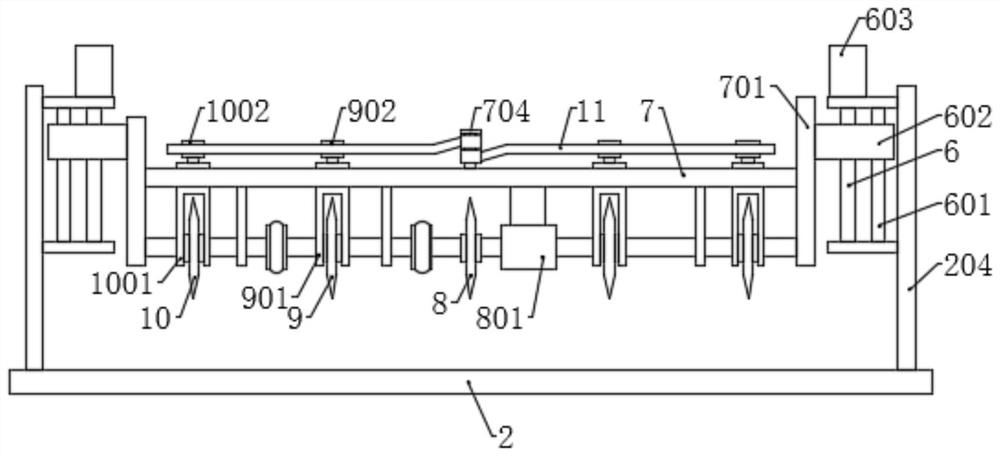
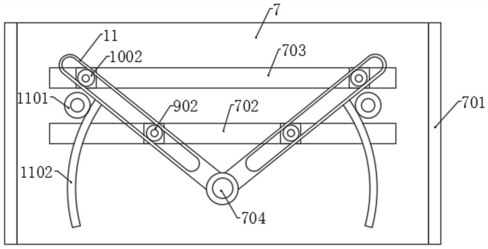
[0036] Such as Figures 1 to 8 As shown, the present invention provides an equidistant cutting device for building wood processing, including a base 1, the left side of the top surface of the base 1 is fixedly connected with a workbench 2 through a first support rod 101, and the right side of the top surface is provided with a The transport assembly, and a turret 4 is provided between the workbench 2 and the conveyance assembly, a hydraulic telescopic cylinder 203 is provided on the left side of the top surface of the workbench 2, and an L-shaped push plate 202 is fixed at the output end of the hydraulic telescopic rod. Two side plates 204 are symmetrically fixed on the left side of the top surface of the workbench 2, and an equidistant cutting mechanism 3 is arranged between the two side plates 204, and the equidistant cutting mechanism 3 includes a As for the lifting assembly, the two lifting assemblies are provided with a lifting plate 7, the bottom surface of the lifting p...
Embodiment 2
[0042] Such as Figure 1 to Figure 8 As shown, the components that are the same as or corresponding to those in the first embodiment are marked with the corresponding reference numerals in the first embodiment. For the sake of simplicity, only the differences from the first embodiment will be described below. The difference between this embodiment two and embodiment one is: as Figures 2 to 4 As shown, the lifting assembly includes a screw rod 6 that is rotatably connected to the inside of the side plate 204. The screw rod 6 is sleeved with a lifting block 602, and one end is connected with a lifting motor 603. One side of the screw rod 6 is also arranged in parallel. There is a guide rod 601, the guide rod 601 is fixedly connected with the side plate 204, and the lifting block 602 is sleeved on the guide rod 601, and slides along the guide rod 601, the inner surface of the lifting block 602 is fixed with a connecting plate 701, and the lifting plate The two ends of 7 are res...
Embodiment 3
[0048] Such as Figure 1 to Figure 8 As shown, the components that are the same as or corresponding to those in the first embodiment are marked with the corresponding reference numerals in the first embodiment. For the sake of simplicity, only the differences from the first embodiment will be described below. The difference between this embodiment two and embodiment one is: as Figure 7 , 8 As shown, one end of the rotating shaft 401 is fixed with a rotating disk 406, the rotating disk 406 is connected with a ratchet 407, and the middle part of the ratchet 407 is connected with the rotating disk 406 through a spring, and the corresponding position on the fixed plate 201 rotates. Connected with a rotating gear 404, the rotating center of the rotating gear 404 coincides with the rotating shaft 401, and an inner ratchet 405 is coaxially fixed on the rotating gear 404, and the ratchet 407 is correspondingly connected with the inner ratchet 405. The hydraulic telescopic cylinder 2...
PUM
 Abstract
Description
Claims
Application Information
 - R&D
- Intellectual Property
- Life Sciences
- Materials
- Tech Scout
- Unparalleled Data Quality
- Higher Quality Content
- 60% Fewer Hallucinations
Browse by: Latest US Patents, China's latest patents, Technical Efficacy Thesaurus, Application Domain, Technology Topic, Popular Technical Reports.
© 2025 PatSnap. All rights reserved.Legal|Privacy policy|Modern Slavery Act Transparency Statement|Sitemap|About US| Contact US: help@patsnap.com


