
Pose tracking method and device

A pose and attitude technology, applied in the field of pose tracking methods and devices, can solve problems such as failure of pose calculation, failure to apply, time-consuming correspondence, etc., to reduce dependencies, reduce delays, improve accuracy and efficiency Effect

Active Publication Date: 2020-02-11
SAMSUNG (CHINA) SEMICONDUCTOR CO LTD +1
View PDF15 Cites 12 Cited by
  • Summary
  • Abstract
  • Description
  • Claims
  • Application Information

AI Technical Summary

Problems solved by technology

However, these methods have some limitations, either the number of LED lights must be four and coplanar, or the calculation ratio exceeds the preset deviation threshold and cannot be applied to real-time systems
Having only 4 LED lights will affect the accuracy of pose tracking and the robustness of the system, because if one of the lights is not detected, the pose solution will fail
In addition, violently solving the correspondence between 2D / 3D point sets is very time-consuming and cannot be applied to situations where there are many LED lights and real-time systems

Method used


Image

  • Pose tracking method and device
  • Pose tracking method and device
  • Pose tracking method and device

Examples


Embodiment Construction

[0029] Reference will now be made in detail to the exemplary embodiments of the present disclosure, examples of which are shown in the drawings, in which the same reference numerals always refer to the same components. The embodiments will be described below in order to explain the present disclosure by referring to the drawings.

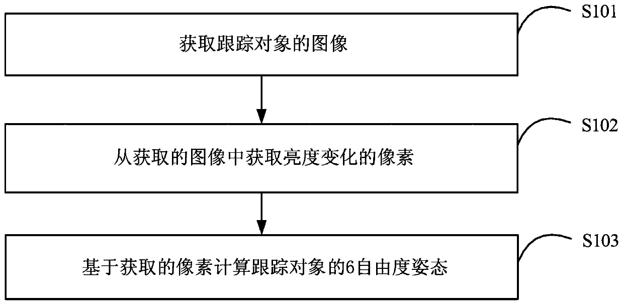
[0030] figure 1 A flowchart of a pose tracking method according to an exemplary embodiment of the present disclosure is shown. figure 1 The pose tracking method shown in is applicable to a tracking object provided with a plurality of markers blinking at a specific frequency, where the marker blinking at a specific frequency may be, for example, an active LED. In the following description, an LED lamp is used as an example of the mark, but it should be understood that the present invention is not limited to this. Those skilled in the art can adopt other forms of marking according to the needs of the embodiment.

[0031] Reference figure 1 , In step S101,...


PUM


Abstract

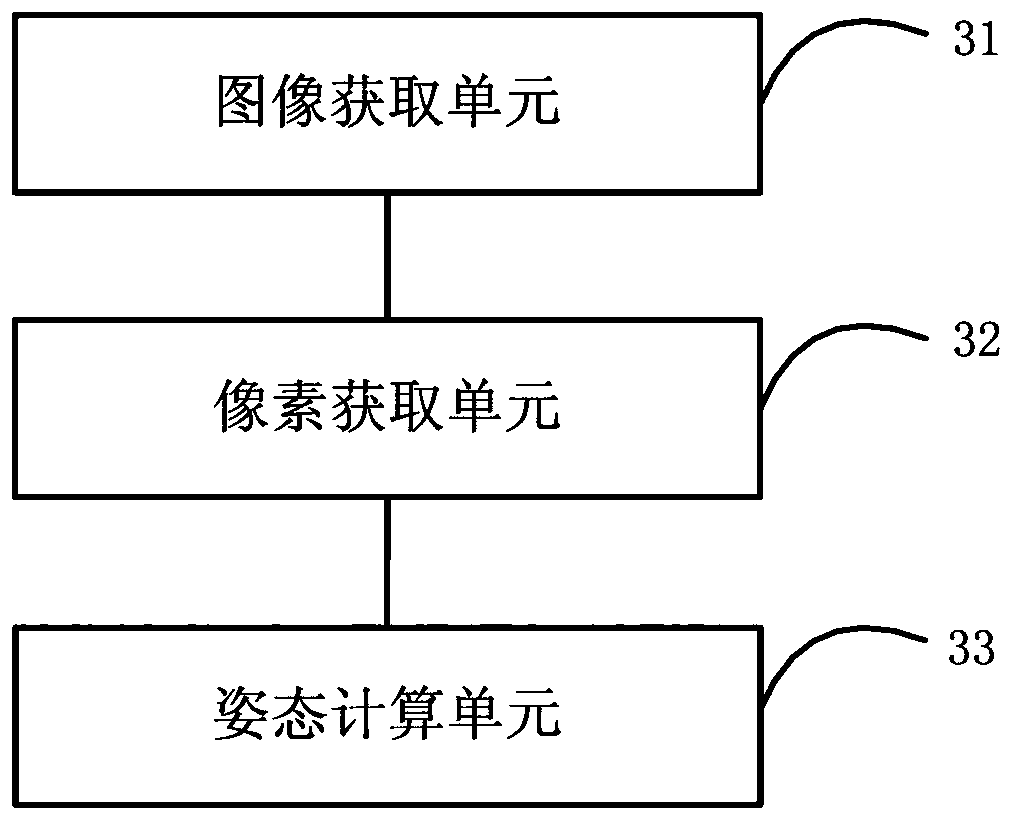
The invention provides a pose tracking method and device. The pose tracking method comprises the steps that an image of a tracking object is acquired, and a mark flickering at a specific frequency isarranged on the tracking object; acquiring pixels of which the brightness changes from the acquired image; the six-degree-of-freedom posture of the tracking object is calculated based on the obtainedpixels, so that the dependence of posture tracking on the specific layout of LED marks is reduced, meanwhile, the delay of posture tracking is reduced, and the precision and efficiency of posture tracking are improved.

Description

Technical field [0001] The present disclosure relates to the field of computer vision technology. More specifically, the present disclosure relates to a pose tracking method and device. Background technique [0002] In recent years, a variety of 6-DOF pose estimation methods have been proposed and are widely used in robot grasping, virtual reality / augmented reality, and human-computer interaction. Virtual reality and augmented reality have high requirements on system latency. If the system reacts sluggishly to head movement, it will cause dizziness and nausea for the user. The delay of Valve's system is 7-15 milliseconds. The current commercial virtual reality (VR) tracking product has the lowest latency of 15 milliseconds, which still does not allow users to have a perfect immersive experience. [0003] Many current optical tracking systems are based on complementary metal oxide semiconductor (CMOS) cameras. But the CMOS camera delay of this kind of consumer machine is genera...

Claims


Application Information

Patent Timeline
Patent Type & Authority Applications(China)
IPC IPC(8): G06T7/70
CPCG06T7/70G06T2207/10012G06T7/246G06T7/73G06F3/011G06F3/0346G06T2207/30204G06T5/70
Inventor 唐创奇李卓李宇光
Owner SAMSUNG (CHINA) SEMICONDUCTOR CO LTD
Learn More