
An integrated optical module bit error tester based on pam4

A technology of bit error test and optical module, applied in the field of optical communication, can solve the problems of large loss of PAM4 signal, difficulty in ensuring high-speed signal integrity, avoid signal integrity problems and economic problems, facilitate product market promotion, high cost effect

Active Publication Date: 2020-11-10
CHINA ELECTRONIS TECH INSTR CO LTD
View PDF4 Cites 0 Cited by
  • Summary
  • Abstract
  • Description
  • Claims
  • Application Information

AI Technical Summary

Problems solved by technology

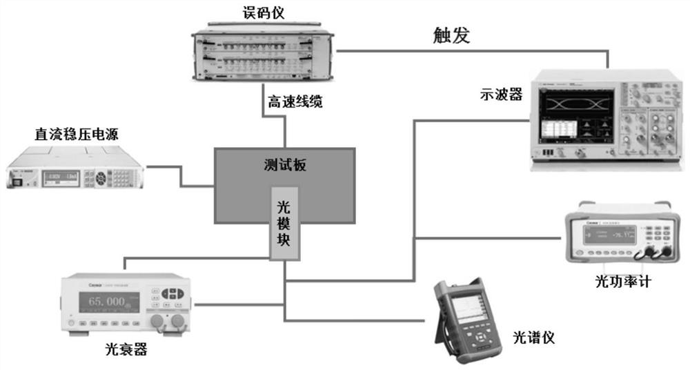
At the same time, with the development of PAM4 technology, more and more optical modules begin to use PAM4 modulation to increase the transmission rate, and the SMA interface optical module error tester is separated from the interface circuit and the error test module, and the transmission rate is more than 50Gbps or the length is relatively long. When the PRBS pattern is long, there is a large loss in the PAM4 signal, and it is difficult to ensure the integrity of the high-speed signal even with expensive high-speed connection cables

Method used


Image

  • An integrated optical module bit error tester based on pam4
  • An integrated optical module bit error tester based on pam4
  • An integrated optical module bit error tester based on pam4

Examples


Embodiment Construction

[0023] It should be pointed out that the following detailed description is exemplary and intended to provide further explanation to the present application. Unless defined otherwise, all technical and scientific terms used herein have the same meaning as commonly understood by one of ordinary skill in the art to which this application belongs.

[0024] It should be noted that the terminology used here is only for describing specific implementations, and is not intended to limit the exemplary implementations according to the present application. As used herein, unless the context clearly dictates otherwise, the singular is intended to include the plural, and it should also be understood that when the terms "comprising" and / or "comprising" are used in this specification, they mean There are features, steps, operations, means, components and / or combinations thereof.

[0025] As mentioned above in the present invention, in the process of using the optical module for communication...


PUM


Abstract

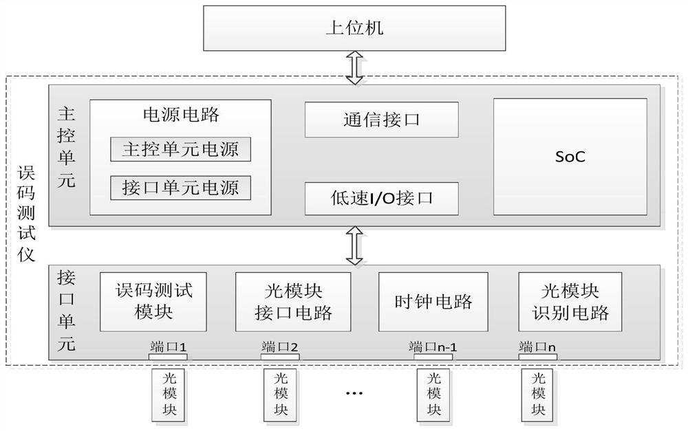
The invention discloses an integrated optical module error code tester based on PAM4. The integrated optical module error code tester comprises a main control unit, an interface unit and an upper computer. By integrating peripheral circuits such as a communication interface, a power supply circuit, an I / O interface and the like into a main control unit, the SoC performs power supply configurationand I / O signal definition according to different optical module types. The interface unit is connected with the main control unit through the pluggable connector, only the interface unit needs to be replaced when different optical module tests are carried out, and corresponding peripheral circuits do not need to be customized. The optical module interface circuit and the error code test module areboth integrated in the interface unit, and no cable is needed for connection, so that the loss in the test process is reduced, and NRZ / PAM4 signals with higher rate and PRBS code patterns with longerlength can be tested.

Description

technical field [0001] The invention relates to the technical field of optical communication, in particular to a PAM4-based integrated optical module bit error tester. Background technique [0002] With the large-scale application of big data, cloud computing and the Internet of Things, data traffic has increased sharply. As a popular signal transmission technology for high-speed signal interconnection in next-generation data centers, PAM4 is widely used in 200G / 400G optical modules. In the process of formulating the new generation of 200G / 400G interface standards, the general appeal is to increase the data rate of each pair of differential lines to more than 50Gbps. If NRZ modulation technology is still used, since each symbol period is less than 20ps, for The time margin of the transceiver chip and the transmission link, as well as the board material and wiring of the printed board are extremely demanding, so the adoption of PAM4 technology has almost become an inevitable ...

Claims


Application Information

Patent Timeline
Patent Type & Authority Patents(China)
IPC IPC(8): H04B10/079H04L1/20
CPCH04B10/07953H04B2210/517H04L1/203H04B10/0799H04B10/524H04B10/541
Inventor 钮鑫胡亚平黄文南李涛
Owner CHINA ELECTRONIS TECH INSTR CO LTD
Learn More