
Melting zone control method based on electric melting connector real-time temperature field data

A technology of electrofusion joints and real-time temperature, which is applied in the direction of pipes/pipe joints/fittings, pipe connection layout, household appliances, etc., which can solve the problems of unstable voltage output and inability to analyze the temperature field of the welding process, etc.

Active Publication Date: 2020-02-14
ZHEJIANG UNIV
View PDF5 Cites 5 Cited by
  • Summary
  • Abstract
  • Description
  • Claims
  • Application Information

AI Technical Summary

Problems solved by technology

But in the actual production process, the voltage output is often not constant. For example, in the initial stage of welding, it takes a certain amount of time to raise the voltage to 39.5V. At the same time, in the constant voltage welding stage, the voltage cannot be guaranteed to be constant 39.5V, tends to fluctuate between 38-41V
As a result, although such models can predict and infer the expansion of the melting zone, they are often only used for prediction in the design stage and cannot be used for the analysis of the temperature field in the welding process.

Method used


Image

  • Melting zone control method based on electric melting connector real-time temperature field data
  • Melting zone control method based on electric melting connector real-time temperature field data
  • Melting zone control method based on electric melting connector real-time temperature field data

Examples


Embodiment

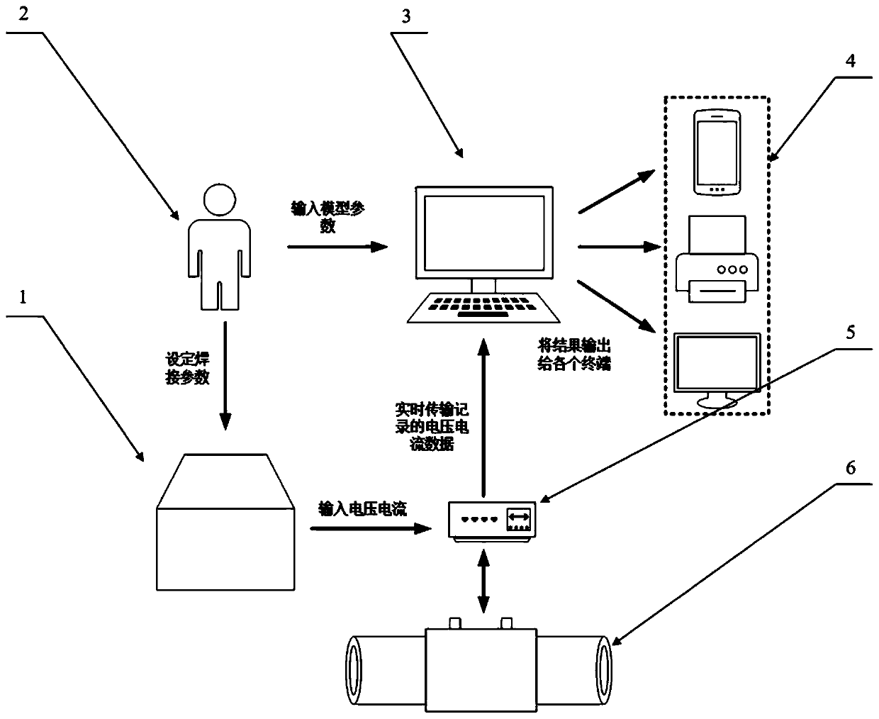
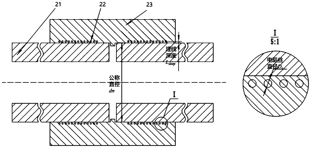
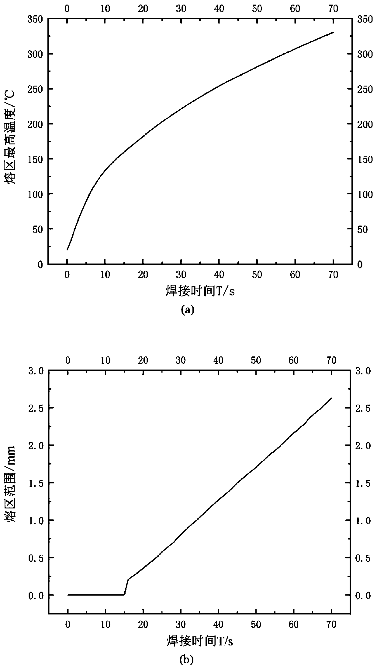
[0099] According to the method for measuring and calculating the temperature field of an electrofusion joint based on real-time welding data provided by the present invention, the temperature field is measured and calculated for an electrofusion joint with a nominal diameter of 63 mm. The nominal diameter of the joint d n 63mm, the total number of resistance wires is 36 (18 on one side), the embedding depth of resistance wires is 0.5mm, the recommended welding voltage is 39.5V, the welding time is 70s, the ambient temperature on site is 20°C, and the standard size ratio The SDR is 11. According to step 1 to step 4 of the method of the present invention, the real-time welding temperature field of the electrofusion joint can be obtained.

[0100] The specific calculation process is as follows:

[0101] 1. The input standard welding voltage in the welding machine is 39.5V, and the welding time is 70s. Apply the known model parameters to the computer.

[0102] 2. Determine the...


PUM


Abstract

The invention relates to the electric melting pipe fitting welding quality evaluation technology, and aims at providing a melting zone control method based on electric melting connector real-time temperature field data. The melting zone control method comprises the steps that welding parameters are utilized for constructing a temperature field calculation model of an electric melting connector; welding process control parameters of the electric melting connector are input into an electric melting welding machine, after welding is started, voltage and current data output by the electric meltingwelding machine in real time are measured and input into the temperature field calculation model, and coordinate data and temperature data of any time and any point in the electric melting connectortemperature field are output in real time; coordinate data of all position points in the melting zone are extracted, and the maximum melting zone depth lmax is calculated; and in the welding process,according to the preset melting zone control section and the real-time changing maximum melting zone depth lmax data, the welding process control parameters are adjusted, and control over the electricmelting connector melting zone coverage area is achieved. By means of the melting zone control method, data support can be provided for accident reason analysis, the melting zone control method is suitable for various electric melting connectors produced by different welding machines and pipe fitting manufacturers, and judgment and welding quality grasping are facilitated.

Description

technical field [0001] The invention relates to the welding quality evaluation technology of electric fusion pipe fittings, in particular to a melting zone control method based on real-time temperature field data of electric fusion joints. Background technique [0002] With the increasing scarcity of oil resources, it is imminent to adjust the structure of energy consumption. After completing the transition from coal to petroleum, the world's energy consumption structure is developing towards clean and efficient natural gas, nuclear energy, solar energy, wind energy and other new energy sources. my country regards the development and utilization of natural gas as the focus of optimizing the energy structure and upgrading the oil industry in the early 21st century, and takes "high efficiency, economy, cleanliness and safety" as the goal of transformation. [0003] In order to achieve this goal, my country has started to implement the "West-to-East Gas Transmission" project s...

Claims


Application Information

Patent Timeline
IPC IPC(8): B29C65/34F16L47/03B29L23/00
CPCB29C65/342B29C66/1122B29C66/1142B29C66/5221B29C66/52272B29C66/91313B29C66/91315B29C66/91651B29L2023/22F16L47/03
Inventor 施建峰胡裕锐郑津洋
Owner ZHEJIANG UNIV
Learn More