Anaerobic medium-temperature lower suction type pyrolysis device

A medium-temperature, pyrolysis technology, applied in special forms of dry distillation, petroleum industry, biofuels, etc., can solve problems such as high energy consumption, influence on combustible gas precipitation effect, and poor control of combustion reaction, so as to ensure airtight effect and reduce cooling Dealing with difficulty and ensuring the effect of uniformity

Pending Publication Date: 2020-02-14
NORTH CHINA UNIV OF WATER RESOURCES & ELECTRIC POWER
View PDF3 Cites 2 Cited by
  • Summary
  • Abstract
  • Description
  • Claims
  • Application Information

AI Technical Summary

Problems solved by technology

[0012] The above-mentioned technical solutions all adopt the conventional gasification furnace arrangement form of oxidation layer, reduction layer, cracking layer and drying layer. However, it is found in the application that since the gasification agent generally uses oxygen-containing normal temperature air, it is introduced into the gas from the lower part of the grate. In the chemical zone, it is difficult to control the combustion reaction, and the temperature is often too high (generally at 1000°C) to exceed the optimum precipitation temperature for the precipitation of combustible gases from biomass, which ultimately affects the precipitation of combustible gases; and the gas export of conventional gasifiers It requires the cooperation of high-power fans to achieve continuous pumping, which consumes a lot of energy

Method used


Image

  • Anaerobic medium-temperature lower suction type pyrolysis device
  • Anaerobic medium-temperature lower suction type pyrolysis device
  • Anaerobic medium-temperature lower suction type pyrolysis device

Examples


Embodiment Construction

[0039] The specific implementation manners of the present invention will be described in detail below in conjunction with the accompanying drawings.

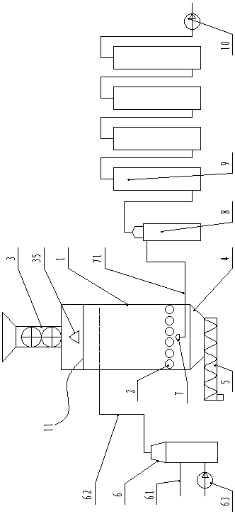
[0040] Such as figure 1 As shown, an oxygen-free medium-temperature downdraft pyrolysis device of the present invention includes a pyrolysis furnace 1, a fire grate 2 is arranged in the pyrolysis furnace 1, and a feed inlet is provided at the pyrolysis furnace 1 above the fire grate 2 , the feed inlet is equipped with a closed feeder 3, the pyrolysis furnace 1 under the grate 2 forms a slag bin 4, the slag bin is provided with a discharge port downward, and a closed feeder is provided at the discharge port. Discharger 5.

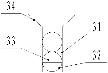
[0041] Such as figure 2 As shown, in the present embodiment, the closed feeder 3 includes a feed cylinder 31 connected to the feed port, the cross section of the feed cylinder 31 is a rectangular structure, and two horizontal cylinders are arranged tangentially up and down in the feed cylinder 31. Arranged...


PUM


Abstract

The invention discloses an anaerobic medium-temperature lower suction type pyrolysis device which comprises a pyrolysis furnace as well as an anaerobic medium-temperature gas source mechanism, whereinthe pyrolysis furnace is internally provided with a grate; a feeding hole is formed above the grate and in the pyrolysis furnace; a sealed feeding device is arranged at the feeding hole in match; a discharge hole is formed below the grate and in the pyrolysis furnace; a sealed discharge device is arranged at the discharge hole in match; the anaerobic medium-temperature gas source mechanism is arranged outside the pyrolysis furnace and is used for providing flue gas into the pyrolysis furnace; the anaerobic medium-temperature gas source mechanism comprises a combustor; a combustible gas collector is arranged on the pyrolysis furnace and below the grate to form a lower suction type structure; and the combustible gas collector is led outside the pyrolysis furnace through a combustible gas collection pipeline. As a medium-temperature field is formed in the pyrolysis furnace, the separation temperature can be effectively controlled, biomass in the pyrolysis furnace can be at an optimal separation temperature for separating a combustible gas, and furthermore, the separation effect of the combustible gas can be ensured.

Description

technical field [0001] The invention relates to the technical field of biomass pyrolysis, in particular to an oxygen-free medium-temperature downdraft pyrolysis device. Background technique [0002] Biomass gasification is under certain thermodynamic conditions, with the help of air (or oxygen) and water vapor, the high polymers of biomass are pyrolyzed, oxidized, reduced and reformed, and finally converted into carbon monoxide and hydrogen. and low molecular weight hydrocarbons and other combustible gases. [0003] The key to biomass gasification lies in the gasifier. The gasifiers currently in use include updraft, downdraft, open and fluidized bed. The reaction process of different biomass is also different. Common gasifier reactions can be divided into oxidation layer, reduction layer, cracking layer and drying layer: [0004] 1) Oxidation layer; the main reaction of biomass in the oxidation layer is oxidation reaction, the gasification agent is introduced from the lowe...

Claims


Application Information

Patent Timeline
Patent Type & Authority Applications(China)
IPC IPC(8): C10B53/00C10B53/07C10C5/00
CPCC10B53/00C10B53/07C10C5/00Y02E50/10Y02P20/143
Inventor 苏钰杰赵廷林关树义
Owner NORTH CHINA UNIV OF WATER RESOURCES & ELECTRIC POWER
Why Eureka
Try Eureka