
Intelligent atomizing nozzle and spraying control system based on high-voltage discharge

A technology of atomizing nozzles and high-voltage discharges, which is applied to jet propulsion devices, rocket engine devices, machines/engines, etc., can solve problems such as delayed response, limited adjustment range, and reduced combustion efficiency, and achieve improved mixing and combustion state, parameters Wide adjustable range, efficient combustion effect

Active Publication Date: 2020-02-14
PLA PEOPLES LIBERATION ARMY OF CHINA STRATEGIC SUPPORT FORCE AEROSPACE ENG UNIV
View PDF6 Cites 3 Cited by
  • Summary
  • Abstract
  • Description
  • Claims
  • Application Information

AI Technical Summary

Problems solved by technology

At present, it is generally believed that straight nozzles have long atomization distance and poor effect, and are basically not used in liquid rocket engines and aero engines; while impact nozzles require multiple jets, and the uniformity of atomization is difficult to guarantee, and they are only used in a few large-scale nozzles. On the engine; the coaxial nozzle is widely used in various aerospace power devices because of its relatively good atomization effect and compact structure.
[0004] However, for a certain type of engine, its nozzle configuration is fixed, and various internal and external factors may cause unpredictable changes in fuel injection parameters during engine operation. When the fuel atomization parameters exceed the normal operating range of the engine In light cases, it will lead to reduced combustion efficiency and engine thrust, and in severe cases, it will lead to ignition failure and even explosion.
Existing solutions usually can only adjust the propellant flow rate, which is difficult to control accurately, has a limited adjustment range, and has problems such as delayed response

Method used


Image

  • Intelligent atomizing nozzle and spraying control system based on high-voltage discharge
  • Intelligent atomizing nozzle and spraying control system based on high-voltage discharge
  • Intelligent atomizing nozzle and spraying control system based on high-voltage discharge

Examples


Embodiment Construction

[0043] The present invention will be further described in detail below in conjunction with the accompanying drawings and specific preferred embodiments.

[0044] In the description of the present invention, it should be understood that the orientations or positional relationships indicated by the terms "left side", "right side", "upper", "lower" are based on the orientations or positional relationships shown in the accompanying drawings, and are only For the purpose of describing the present invention and simplifying the description, rather than indicating or implying that the device or element referred to must have a specific orientation, be constructed and operate in a specific orientation, "first", "second" and the like do not represent components importance, and therefore should not be construed as limiting the invention. The specific dimensions used in this embodiment are only for illustrating the technical solution, and do not limit the protection scope of the present in...


PUM


Abstract

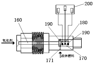
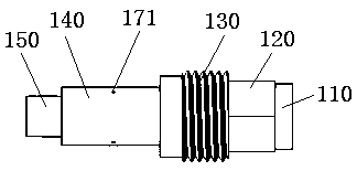
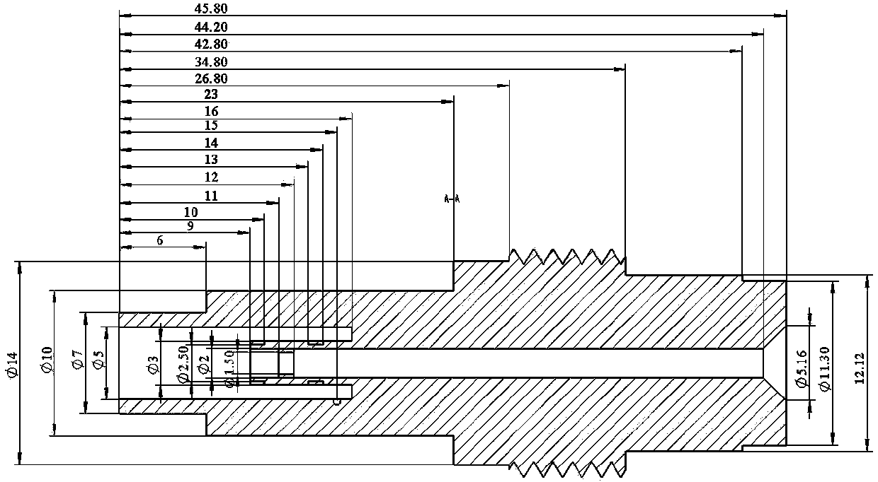
The invention discloses an intelligent atomizing nozzle and a spraying control system based on high-voltage discharge. The intelligent atomizing nozzle comprises an inner fluid passageway, an outer fluid passageway, a high-voltage electrode, two low-voltage electrodes and a high-voltage power source. The outer fluid passageway is used for introducing liquid fuel. The inner fluid passageway is usedfor introducing a gas oxidizing agent, the downstream tail end of the inner fluid passageway is shorter than the outer fluid passageway, and a retraction region is formed. The high-voltage electrodeand the two low-voltage electrodes are annular and are connected with the high-voltage power source. The high-voltage electrode is arranged in the portion, close to the tail portion, of the inner fluid passageway, and the outer wall face of the high-voltage electrode is attached to the inner wall face of the inner fluid passageway. The two low-voltage electrodes are nested in the portions, at theupstream end and the downstream end of the high-voltage electrode, of the outer wall face of the inner fluid passageway at equal intervals. The high-voltage electrode communicates with any low-voltageelectrode to form a discharge exciter. Plasma induced jet flow in two directions can be formed by the two discharge exciters. Parameters such as the atomizing angle and the diameters of atomized liquid drops can be rapidly adjusted according to the requirements, and then the atomizing effect is effectively controlled.

Description

technical field [0001] The invention relates to the field of aerospace power devices, in particular to an intelligent atomizing nozzle and spray control system based on high-voltage discharge. Background technique [0002] In aircraft power devices such as liquid rocket engines and aeroengines, liquid kerosene is usually used as fuel, and the liquid fuel is sprayed from the nozzle of the combustion chamber, and it has to go through several sub-processes of atomization, evaporation, mixing, and combustion. Among them, as the first sub-process, atomization is directly related to other subsequent sub-processes, and then affects the success or failure of ignition, flame stability, and combustion efficiency in the combustion chamber of the engine. Specifically, when the atomized liquid droplets produced by the nozzle are too large, rough combustion may occur, the evaporation time becomes longer, and ignition is difficult; when the atomized liquid droplets are too fine, it may lea...

Claims


Application Information

Patent Timeline
Patent Type & Authority Applications(China)
IPC IPC(8): F02K9/52F02K9/56
CPCF02K9/52F02K9/56
Inventor 周思引田园聂万胜陈朋
Owner PLA PEOPLES LIBERATION ARMY OF CHINA STRATEGIC SUPPORT FORCE AEROSPACE ENG UNIV
Learn More