
Dynamic precision detection method under complex motion state of five-axis machine tool based on double-ball-bar

A complex motion and dynamic precision technology, applied in the testing of machines/structural components, instruments, measuring devices, etc., can solve problems such as single evaluation index, single motion mode of machine tools, and inability to fully reflect the dynamic characteristics of machine tools, etc., to achieve comprehensive testing and evaluate, accurately reflect the effect of

Active Publication Date: 2020-02-14
UNIV OF ELECTRONICS SCI & TECH OF CHINA
View PDF6 Cites 8 Cited by
  • Summary
  • Abstract
  • Description
  • Claims
  • Application Information

AI Technical Summary

Problems solved by technology

The above detection scheme has the advantages of simple detection process and short detection time, but there are some defects: firstly, the motion mode of the machine tool in this detection scheme is too single, and it is difficult to fully reflect the dynamic performance of the machine tool under the actual processing state; secondly, the ballbar The detection results are jointly affected by several types of errors such as geometric errors, thermal deformation errors, and dynamic errors, and it is difficult to detect and analyze the impact of dynamic errors alone; in addition, only the difference between the maximum value and the minimum value is used as the evaluation index of the dynamic performance of the machine tool , the evaluation index is relatively single and cannot fully reflect the dynamic characteristics of the machine tool. Therefore, it is necessary to improve the existing detection scheme

Method used


Image

  • Dynamic precision detection method under complex motion state of five-axis machine tool based on double-ball-bar
  • Dynamic precision detection method under complex motion state of five-axis machine tool based on double-ball-bar
  • Dynamic precision detection method under complex motion state of five-axis machine tool based on double-ball-bar

Examples


Embodiment Construction

[0044] The technical solution of the present invention will be further described below in conjunction with the accompanying drawings.

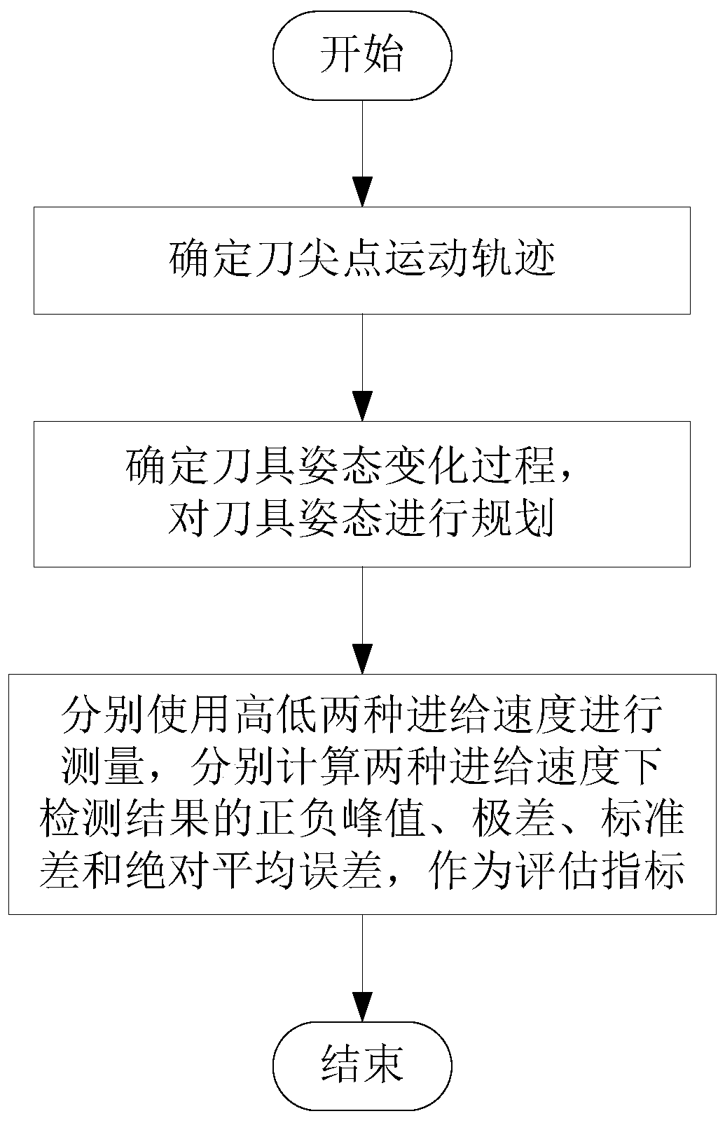
[0045] Such as figure 1 As shown, a ballbar-based five-axis machine tool dynamic accuracy detection method in a complex motion state of the present invention includes the following steps:

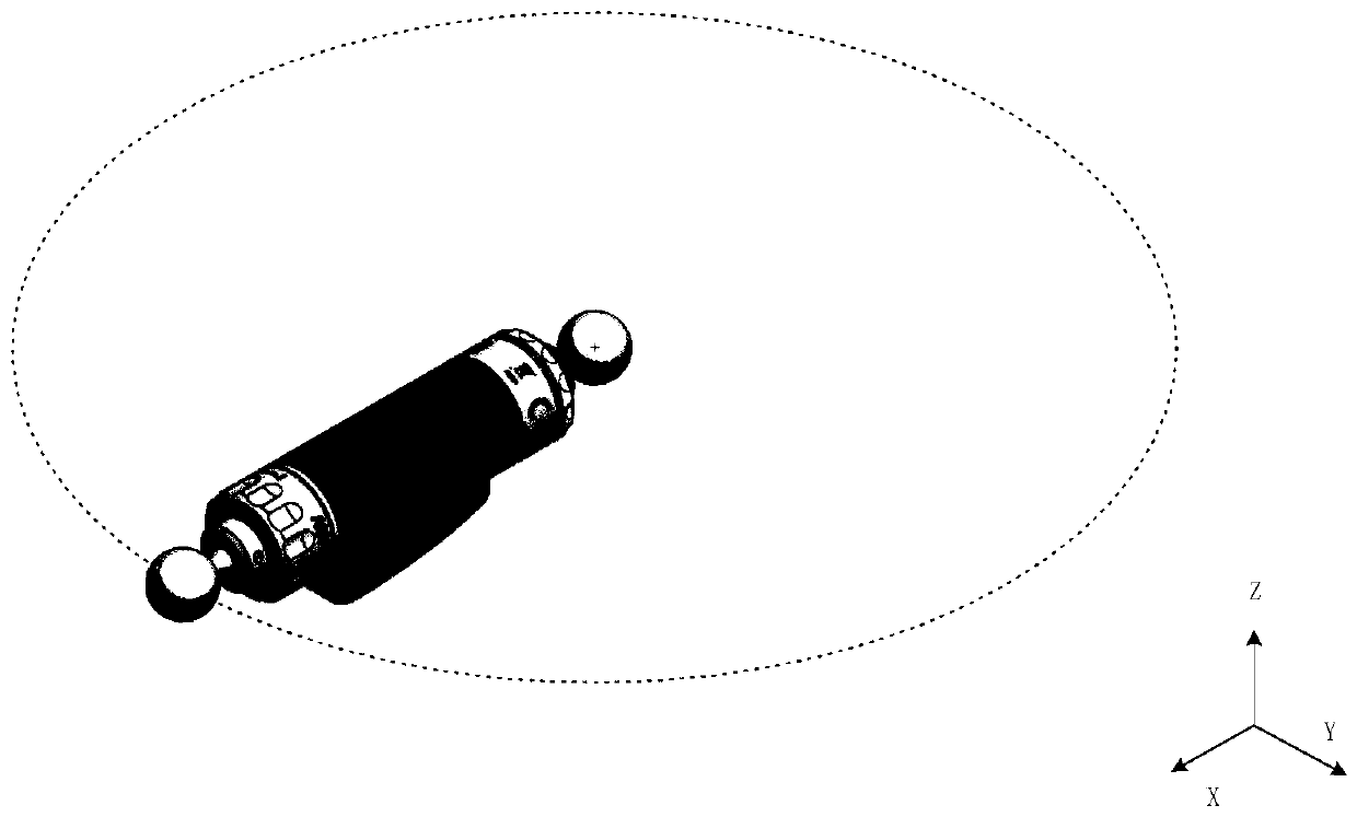
[0046] S1. Determine the motion trajectory of the tool tip point; for the planning of the tool tip point position, in order to ensure that the ideal distance between the two ballbars of the ballbar remains unchanged during measurement, set the tool tip point to perform circular interpolation movement, such as figure 2 As shown, the motion trajectory (X, Y, Z) of the tool nose point is obtained as:

[0047]

[0048] θ∈[0,2π]

[0049] Among them, R is the ideal distance between the two ball heads of the ballbar, (x 0 ,y 0 ,z 0 ) is the fixed position of the ball of the ballbar on one side of the table, θ is the rotation angle of the bar;

[0050] In...


PUM


Abstract

The invention discloses a dynamic precision detection method under a complex motion state of a five-axis machine tool based on a double-ball-bar. The method comprises the following steps of step S1, determining the motion trajectory of a tool tip point; determining a tool attitude change process and planning the tool attitude; and step S3, respectively using high and low feed speeds to measure, and respectively calculating positive and negative peak values, a range, a standard deviation and an absolute average error of a detection result under two feed speeds as evaluation indexes. The dynamicprecision detection method provided by the invention comprises a richer motion state and a motion mode, and helps to detect and evaluate the dynamic precision of a five-axis numerical control machinetool more quickly, accurately and comprehensively; the parts affected by dynamic errors in tool tip point offset are separated by means of differential measurement, so that the impact of the dynamicperformance can be extracted, and the influence of geometric errors as miscellaneous errors in the dynamic performance evaluation can be reduced.

Description

technical field [0001] The invention belongs to the technical field of five-axis numerical control machining, and in particular relates to a ballbar-based dynamic precision detection method of a five-axis machine tool in a complex motion state. Background technique [0002] CNC machine tools are the foundation of modern manufacturing, and the precision of CNC machine tools will directly affect the precision of processed products. Five-axis CNC machine tools, as the name suggests, add two rotating axes to the traditional three-axis machine tools, so that they can process complex curved surfaces, and are widely used in aircraft parts, impellers and propellers, etc. The processing has an important influence in aerospace, precision instruments and other fields. For five-axis CNC machine tools, compared with other error types, the dynamic error caused by the dynamic performance defect of the servo system is the most important factor affecting the machining accuracy in the proces...

Claims


Application Information

Patent Timeline
Patent Type & Authority Applications(China)
IPC IPC(8): G01M99/00G01B21/00
CPCG01B21/00G01M99/008
Inventor 丁杰雄李昊卿黄卓丁启程杜丽王伟姜忠孟国栋张靖
Owner UNIV OF ELECTRONICS SCI & TECH OF CHINA
Learn More