Backbone prosthesis with supination-type expansion tube structure handle and using method thereof

A tube expansion and backbone technology, applied in the direction of prosthesis, femur, femoral head, etc., can solve the problems of increased trauma, increased operation difficulty and operation time, postoperative stress concentration, etc., to improve rigid confrontation, increase surgical trauma, local The effect of diameter increase

Pending Publication Date: 2020-02-21
胡永成
View PDF10 Cites 0 Cited by
  • Summary
  • Abstract
  • Description
  • Claims
  • Application Information

AI Technical Summary

Problems solved by technology

[0006] At present, in view of the shortcomings of poor early stability of biological fixed prosthesis stems, some prostheses have been improved, mainly by adding steel plates and screw structures to achieve early stability of the prosthesis
However, there are still many defects and related complications in these prostheses: increased surgical exposure area, increased trauma, difficulty in screw placement, increased surgical difficulty and operation time, difficulty in matching the implanted prosthetic stem with the medullary cavity, and the prosthetic stem. Disadvantages such as difficulty in adjusting the line of force, postoperative stress concentration, and high risk of plate and screw fracture

Method used


Image

  • Backbone prosthesis with supination-type expansion tube structure handle and using method thereof
  • Backbone prosthesis with supination-type expansion tube structure handle and using method thereof
  • Backbone prosthesis with supination-type expansion tube structure handle and using method thereof

Examples


Embodiment Construction

[0050] In order to enable those skilled in the art to better understand the technical solutions of the present invention, the specific implementation manners of the present invention will be further described below in conjunction with the accompanying drawings.

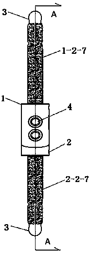
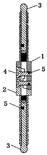
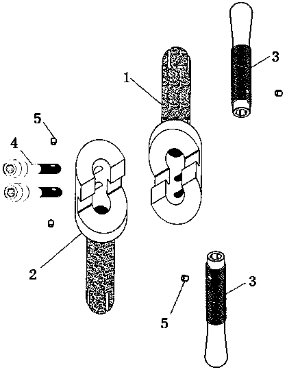
[0051] like Figure 1 to Figure 10 As shown, a backbone prosthesis of a supination type expansion tube structure handle, including a proximal part 1, a distal part 2, an expansion bolt 3, a connecting bolt 4 and an anti-rotation plunger 5;

[0052] The proximal part 1 is composed of a reconstructed part I1-1 with an integral structure and a hollow handle part I1-2;

[0053] The distal part 2 is composed of a reconstructed part II2-1 with an integral structure and a hollow handle part II2-2.

[0054] The base end of the reconstruction part I1-1 is a cylinder I1-1-1, the connecting end is a semi-cylindrical I1-1-2, and a semicircular groove I1-1 is vertically arranged on the plane of the semi-cylindrical I1-1-2 -3, tw...


PUM


Abstract

The invention relates to a backbone prosthesis of a supination-type expansion tube structure handle and a using method thereof, and the using method comprises the following steps: firstly, excising bone tissue of a femur shaft involved by a tumor, screwing a cylindrical end of an expansion bolt into a threaded hole I, and placing a circular cone body of the expansion bolt outside an expansion holeI; screwing the cylindrical end of the other expansion bolt into a threaded hole II, and arranging the circular cone body of the expansion bolt outside the expansion hole II; inserting a handle partI of the near-end part into a backbone medullary cavity at the upper end of a femur, anticlockwise rotating the expansion bolt to enable the circular cone body of the expansion bolt to enter the expansion hole I of the handle part I, and expanding the four blades I to be in close press fit with the bone wall of the medullary cavity; inserting a handle part II of the far-end part into the backbonemedullary cavity at the lower end of the femur, rotating the expansion bolt counterclockwise to enable the circular cone body of the expansion bolt to enter the expansion hole II of the handle part II, and expanding the four blades II to be in close press fit with the bone wall of the medullary cavity; and a reconstruction part I of the near-end part and a reconstruction part II of the far-end part are fixed together. The postoperative immediate three-dimensional stability of the prosthesis handle is achieved.

Description

technical field [0001] The invention relates to a backbone prosthesis of a supination-type expansion tube structure handle and a method for using it. The pressure and friction force between the prosthesis handle and the bone wall can be rapidly increased through the expansion tube structure handle, and the distance between the prosthesis handle and the long bone marrow cavity can be achieved. The close contact can effectively resist the rotation and pulling of the prosthesis, so as to realize the early, medium and long-term three-dimensional stability of the prosthesis. Background technique [0002] With the maturation of joint and bone prosthesis in terms of design, materials, manufacturing and surgical techniques, the application of prosthesis treatment in clinical treatment is increasing. The common application fields of artificial prosthesis include: end-stage joint disease, senile fracture, bone defect after bone tumor resection, severe fracture traumatic disease, etc. ...

Claims


Application Information

Patent Timeline
Patent Type & Authority Applications(China)
IPC IPC(8): A61F2/28A61F2/30A61F2/36
CPCA61F2/28A61F2/30942A61F2/3662A61F2002/30985A61F2002/2825
Inventor 田东牧赵云龙张浩然胡永成考月岗任志鹏张净宇李建军王丰杨雄刚庞承刚
Owner 胡永成
Why Eureka
Try Eureka