System for simultaneously carrying out confining pressure and back pressure to realize high pressure in micro-fluidic chip

A microfluidic chip, medium and high pressure technology, applied in the field of multiphase flow, can solve the problems such as the pressure difference cannot be too large, the loss is strong, and the realization of the confining pressure is small, and the system is simple, the operability is strong, and the system is reduced. The effect of cost

Active Publication Date: 2020-02-21
DALIAN UNIV OF TECH
View PDF4 Cites 3 Cited by
  • Summary
  • Abstract
  • Description
  • Claims
  • Application Information

AI Technical Summary

Problems solved by technology

Among them, the microscopic visualization technology can truly realize the in-situ observation and direct recording of the flow process, which greatly promotes the related research process, but most of the micro-flow research takes place on the microfluidic chip, and most of these chips cannot bear due to the material properties. High pressure, unable to truly realize flow measurement under actual working conditions
[0003] At present, there are two main ways to solve this problem. One is to add a clamp at the inlet and outlet of the microfluidic chip to prevent the port from bursting, but it cannot solve the problem from the root cause, and the withstand pressure cannot be increased too much, and the cost It is relatively expensive and equipped with a dedicated chip, which is extremely lossy; another way is to achieve the preset pressure of the oil recovery confining pressure, and achieve the high pressure through the control of the internal and external pressure difference of the microfluidic chip. Rarely, Chinese invention patent specifications 2012101483096 and 2017113800102 mention the realization of confining pressure, but their purpose is mainly to achieve high pressure in the core through confining pressure, which is not suitable for fragile materials such as glass and PDMS. Chinese invention patent The high-pressure system proposed in the manual 2017107179868 is currently the most commonly used confining pressure method to achieve high pressure. However, it can be found that the design of the confining pressure chamber is complicated, and there are multiple connection parts, which is easy to cause pressure leakage, which is expensive, and realizes confining pressure. The best way is to artificially control the pressure difference between the inside and outside of the microfluidic chip so that there is a certain difficulty in operability.
In addition, there is no outlet when using this system to inject oil or other fluids, which is far from the actual oil and gas recovery, that is, there is no back pressure adjustment part

Method used


Image

  • System for simultaneously carrying out confining pressure and back pressure to realize high pressure in micro-fluidic chip
  • System for simultaneously carrying out confining pressure and back pressure to realize high pressure in micro-fluidic chip

Examples


Embodiment Construction

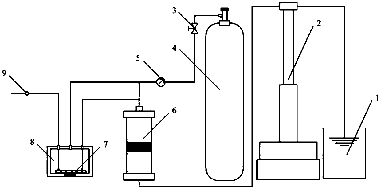
[0018] In order to make the purpose, technical solution and advantages of the system of the present invention clearer, the system of the present invention will be further described in detail below in conjunction with the specific example "Microcosmic visualization system for CO2 displacement of brine under high temperature and high pressure". It should be understood that the specific embodiments described here are only used to explain the system of the present invention, and are not intended to limit the system of the present invention.

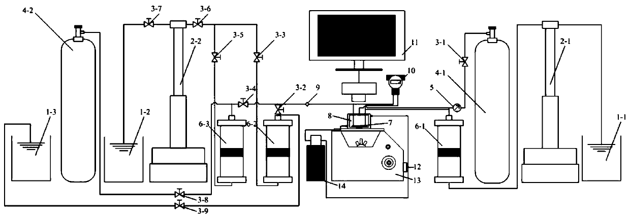
[0019] attached figure 2 in the attached figure 1 The injection system is added on the basis of the experiment, and all valves are closed by default before the experiment starts. When the valve g3-7 is opened, the plunger pump a2-1 and plunger pump b2-2 will suck the liquid container a1-1 and the liquid container Release the liquid in the container b1-2 for pressurization, then close the valve g3-7. Turn on the circulating water bath 14 to...


PUM


Abstract

The invention belongs to the technical field of multiphase flow in primary subject power engineering and engineering thermophysics, and provides a system for simultaneously carrying out confining pressure and back pressure to realize high pressure in a micro-fluidic chip, the system comprises a liquid container, a plunger pump, a valve, a gas cylinder, a pressure gauge, an intermediate piston container, the micro-fluidic chip, a sapphire confining pressure chamber and a pipeline. According to the system disclosed by the invention, confining pressure and back pressure adjustment can be carriedout on the confining pressure chamber which is simple in process manufacturing only by one plunger pump, one middle piston container and one one-way valve; high pressure is truly achieved through simultaneous internal and external pressurization of the micro-fluidic chip, the system is simple and high in operability, potential safety hazards do not exist, and the cost of the system is greatly reduced while the confining pressure function and the backpressure function are achieved at the same time.

Description

technical field [0001] The invention belongs to the technical field of multiphase flow in the first-level subject power engineering and engineering thermophysics, and more specifically, relates to a simple system for simultaneous realization of high pressure, confining pressure and back pressure in microfluidic chips in microscale flow . Background technique [0002] In recent years, microscopic multiphase flow in porous media has been a research hotspot in the fields of science and engineering. Among them, the microscopic visualization technology can truly realize the in-situ observation and direct recording of the flow process, which greatly promotes the related research process, but most of the micro-flow research takes place on the microfluidic chip, and most of these chips cannot bear due to the material properties. High pressure, can not really realize the flow measurement under actual working conditions. [0003] At present, there are two main ways to solve this pro...

Claims


Application Information

Patent Timeline
Patent Type & Authority Applications(China)
IPC IPC(8): B01L3/00
CPCB01L3/502769B01L2400/0478
Inventor 宋永臣赵常忠张毅郑嘉男池渊
Owner DALIAN UNIV OF TECH
Why Eureka
Try Eureka