
Automatic machining device for internal medicine drainage bodies

A technology of automatic processing and fluid drainage, applied in metal processing equipment, metal processing, drilling/drilling equipment, etc., can solve the problems of inability to automatically collect debris, low production efficiency and machining accuracy, and generation of debris.

Active Publication Date: 2020-02-21
成都市双流区第一人民医院
View PDF6 Cites 6 Cited by
  • Summary
  • Abstract
  • Description
  • Claims
  • Application Information

AI Technical Summary

Problems solved by technology

[0004] In order to meet the needs of drainage, a plurality of drainage inlet holes 230 and air pressure balance holes 260 must be opened on the circumference of the tube body 200 of the thin-walled drainage body. The opening of these holes needs to meet the corresponding requirements. In its production and processing procedures , it is necessary to drill multiple times on the tube body 200 of the drainage body to realize the processing of the liquid inlet hole. According to the inlet pipes of different specifications and diameters, the diameters of the processed liquid inlet holes are also relatively different, so they need to be replaced during processing. Drills of various specifications are currently being processed by manual drilling and manual replacement of drill bits. The production efficiency and processing accuracy are low, and debris will be generated while drilling. The existing processing methods cannot be processed. Debris is automatically collected

Method used


Image

  • Automatic machining device for internal medicine drainage bodies
  • Automatic machining device for internal medicine drainage bodies
  • Automatic machining device for internal medicine drainage bodies

Examples


Embodiment Construction

[0035] The technical solutions of the present invention will be further described below in conjunction with the accompanying drawings and through specific implementation methods.

[0036] Wherein, the accompanying drawings are only for illustrative purposes, showing only schematic diagrams, rather than physical drawings, and should not be construed as limitations on this patent; in order to better illustrate the embodiments of the present invention, some parts of the accompanying drawings will be omitted, Enlargement or reduction does not represent the size of the actual product; for those skilled in the art, it is understandable that certain known structures and their descriptions in the drawings may be omitted.

[0037] In the drawings of the embodiments of the present invention, the same or similar symbols correspond to the same or similar components; , "inner", "outer" and other indicated orientations or positional relationships are based on the orientations or positional ...


PUM


Abstract

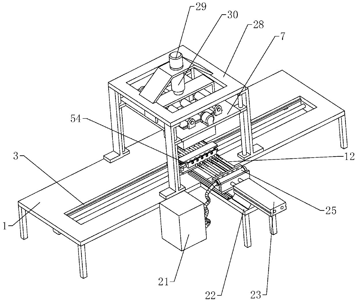
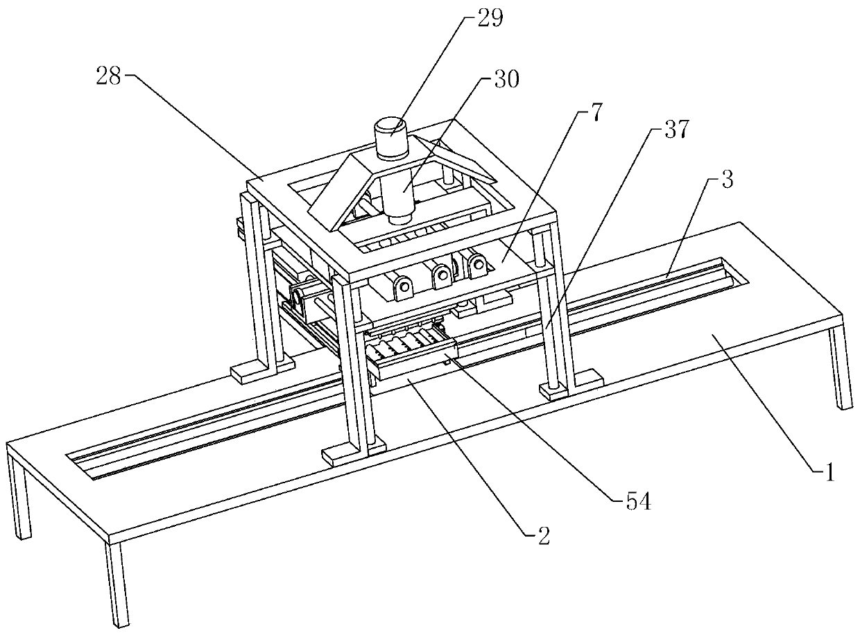
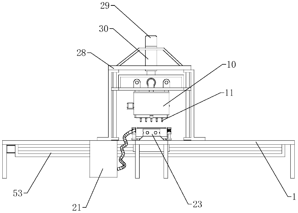
The invention relates to the technical field of medical tool processing, in particular to an automatic machining device for internal medicine drainage bodies. The device comprises a machining table, ahorizontal moving assembly is arranged on the machining table, the horizontal moving assembly comprises a movable plate which can move horizontally, a rectangular containing jig is arranged on the movable plate, a plurality of drainage body containing grooves are formed in the containing jig, a clamping assembly is arranged on the containing jig, a lifting assembly is arranged above the containing jig, the lifting assembly comprises a lifting frame capable of ascending and descending, a longitudinal horizontal moving assembly is arranged at the top of the lifting frame, and the lower portionof the longitudinal horizontal moving assembly is provided with a drill bit replacing mechanism which comprises a reversing assembly, a first perforating assembly and a second perforating assembly. Afragment collecting assembly is arranged on one side of the lower side of the reversing box. According to the automatic machining device, automatic drilling can be carried out on the drainage bodies at the same time, all the holes in pipes of the drainage bodies can be machined in the one-time clamping process, chippings generated by machining can be automatically collected, and the production efficiency and the machining precision are improved.

Description

technical field [0001] The invention relates to the technical field of medical appliance processing, in particular to an automatic processing device for internal medicine drainage fluid. Background technique [0002] Drainage is a medical auxiliary tool commonly used in internal medicine. It is used to drain pus, blood or tissue fluid in the patient's lesion. The shape of the drainage is cylindrical. For specific shapes, see the attached Figure 13 As shown, in order to achieve a better drainage function, it is necessary to open multiple drainage holes on the drainage body, specifically as Figure 13 shown in Figure 13 Among them, the tube body 200 of the drainage body is a thin-walled cylinder, and a puncture needle 240 and a puncture inlet 250 are arranged at the front end of the tube body, and a connecting end 280 is arranged at the rear end of the tube body, and on the connecting end 280 A connecting thread 290 is provided through which the drainage body is connected to ...

Claims


Application Information

Patent Timeline
Patent Type & Authority Applications(China)
IPC IPC(8): B23B41/00B23B47/30B23B47/06B23B47/20B23Q7/00B23Q3/06B23Q11/00B23Q1/26
CPCB23B41/00B23B47/30B23Q1/26B23Q3/062B23Q5/10B23Q5/34B23Q7/00B23Q11/0046
Inventor 赵洪珍
Owner 成都市双流区第一人民医院
Learn More