Continuous rail occupation checking system based on fiber bragg grating sensing technology

A fiber grating and sensing technology technology, which is applied in the use of optical devices to transmit sensing components, convert sensor outputs, instruments and other directions, can solve the problem that axle counting cannot realize continuous track occupancy inspection and other problems, achieve good anti-theft effect, and realize train The effect of convenient positioning and construction

Pending Publication Date: 2020-02-21
CRSC RESEARCH & DESIGN INSTITUTE GROUP CO LTD
View PDF0 Cites 7 Cited by
  • Summary
  • Abstract
  • Description
  • Claims
  • Application Information

AI Technical Summary

Problems solved by technology

The track circuit is affected by lightning, traction current, rail transmission parameters, ballast bed resistance, wheel-rail contact resistance, cable attenuation, etc.; axle counting cannot realize continuous track occupancy inspection, and is also affected by lightning, electromagnetic compatibility and other operating environments

Method used


Image

  • Continuous rail occupation checking system based on fiber bragg grating sensing technology
  • Continuous rail occupation checking system based on fiber bragg grating sensing technology
  • Continuous rail occupation checking system based on fiber bragg grating sensing technology

Examples


no. 1 approach

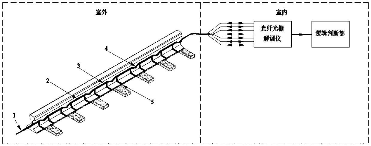
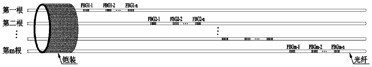
[0064] First embodiment: For example, the optical cable is composed of m optical fibers, and the optical cable can record m groups of FBG sensors, each group of sensors contains n FBG sensors, and each group of sensors is distributed from near to far in space; the FBG sensors of each group are distributed in In the same optical fiber, the FBG sensors in each group are connected in series, and the working wavelengths of the FBG sensors in each group are different; figure 2 and image 3 As shown, Group 1 FBG sensors include FBG 1-1 、FBG 1-2 ...FBG 1-n , Group 2 FBG sensors include FBG 2-1 、FBG 2-2 ...FBG 2-n , and so on, the mth group of FBG sensors includes FBG m-1 、FBG m-2 ...FBG m-n ; The working wavelength of each FBG sensor in the first group is different, and the wavelength of each FBG sensor in the first group is λ 1 , lambda 2 ... λ n ; The working wavelengths of the FBG sensors in the second group are different, and the wavelengths in the second group are re...

no. 2 approach

[0065] Second embodiment: For example, the optical cable is composed of m optical fibers, and the optical cable can record n ​​groups of FBG sensors, each group of sensors contains m FBG sensors, and each group of sensors is distributed from near to far in space; the FBG sensors of each group are distributed in In different optical fibers, the working wavelengths of the FBG sensors in each group are the same. Such as Figure 4 and Figure 5 As shown, Group 1 FBG sensors include FBG 1-1 、FBG 2-1 ...FBG m-1 , Group 2 FBG sensors include FBG 1-2 、FBG 2-2 ...FBG m-2 , and so on, the nth group of FBG sensors includes FBG 1-n 、FBG 2-n ...FBG m-n ; The working wavelength of each FBG sensor in the first group is the same, and the wavelength of each FBG sensor in the first group is λ 1 ; The working wavelength of each FBG sensor in the second group is the same, and the wavelength of each FBG sensor in the second group is λ 2 ; By analogy, the working wavelength of each FBG s...


PUM


Abstract

The invention provides a continuous rail occupation checking system based on a fiber bragg grating sensing technology. Sufficiently dense fiber bragg grating sensors are paved along a rail, and the fiber bragg grating sensors realize continuous rail occupation checking by measuring pressure strain generated by vehicle wheels on the occupied rail. Through the special packaging and design of the sensors, the sensing range of each sensing point can be enlarged to the maximum extent. Through the reasonable arrangement of the sensors, the generation of dead segments can be avoided, and the continuous rail occupation checking is realized. The checking system is not influenced by the external using environments such as lightning, traction current, rail transmission parameters, track bed resistance and wheel rail contact resistance. The continuous rail occupation checking system does not need to pave cables, saves the investment, and has a good anti-theft effect. Through the adoption of the continuous rail occupation checking system, a relay does not need to be provided separately; indoor equipment is reduced; the engineering investment is reduced; and the problem of high cost of the existing rail occupation checking equipment is solved. Moreover, an optical cable is fixed by a clamping tool, so that damage to the rail is reduced, and convenience is brought to the construction.

Description

technical field [0001] The invention belongs to the technical field of track occupancy inspection, in particular to a continuous track occupancy inspection system based on fiber grating sensing technology. Background technique [0002] The track occupancy inspection device is the key basic equipment of the railway signal system, and the most widely used is the track circuit and axle counting track occupancy inspection device (hereinafter referred to as "axle counting"). The track circuit and axle counter transmit control signals through cables to judge the track occupancy and realize the train positioning function, but the project cost is relatively high. The track circuit is affected by lightning, traction current, rail transmission parameters, ballast bed resistance, wheel-rail contact resistance, cable attenuation, etc.; axle counting cannot realize continuous track occupancy inspection, and is also interfered by lightning, electromagnetic compatibility and other operatin...

Claims


Application Information

Patent Timeline
Patent Type & Authority Applications(China)
IPC IPC(8): G01D5/353B61L1/18B61L1/16
CPCB61L1/166B61L1/181G01D5/35316
Inventor 潘继军陈立华靖焱林李铭李闯赵泽谭婧雯
Owner CRSC RESEARCH & DESIGN INSTITUTE GROUP CO LTD
Why Eureka
Try Eureka