Structured light illumination multi-focal-plane three-dimensional super-resolution imaging system

A structured light illumination, super-resolution technology, applied in the field of microscopy, can solve the problem of mixing fluorescent images, and achieve the effect of improving the imaging speed

Inactive Publication Date: 2020-02-21
INSITUTE OF BIOPHYSICS CHINESE ACADEMY OF SCIENCES
View PDF7 Cites 4 Cited by
  • Summary
  • Abstract
  • Description
  • Claims
  • Application Information

AI Technical Summary

Problems solved by technology

However, due to the technical characteristics of the microscope itself, fluorescence images of different focal planes are usually mixed together, requiring a specially designed imaging structure for imaging

Method used


Image

  • Structured light illumination multi-focal-plane three-dimensional super-resolution imaging system
  • Structured light illumination multi-focal-plane three-dimensional super-resolution imaging system
  • Structured light illumination multi-focal-plane three-dimensional super-resolution imaging system

Examples


Embodiment 1

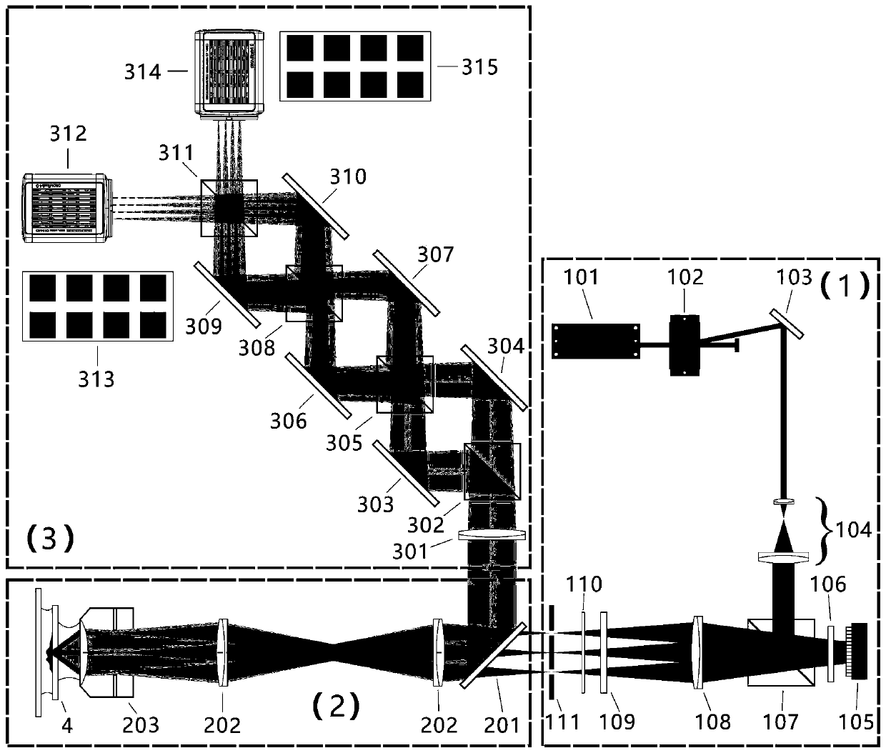
[0048] see figure 1 , a multi-focal plane three-dimensional super-resolution imaging system with structured light illumination, including an excitation light modulation module 1, a microscopic amplification module 2 and a multi-focal plane imaging module 3, the excitation light modulation module 1 is used to modulate the excitation light to a specified state After that, it is sent to the micro-amplification module 2; the micro-amplification module 2 is used to illuminate the sample 4 with the modulated excitation light, perform microscopic observation on the sample 4, and transmit the collected fluorescence signal of the sample 4 to the multi-focus Surface imaging module 3; the multi-focal plane imaging module 3 includes a focus-increasing beam-splitting component and a fluorescence detector, and the focus-increasing beam-splitting component is used to divide the fluorescence signal into multiple beams of signal light with different propagation directions and focusing degrees, ...

Embodiment 2

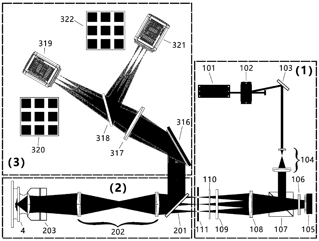
[0060] Referring to Example 1, the structured light illumination multi-focal plane 3D super-resolution imaging system provided in this example is different from it in that, see figure 2 , the focus-increasing spectroscopic assembly includes a reflective diffraction element 316 and a second lens 317, and the reflective diffraction element 316 is used to reflect the fluorescent signal output by the micro-amplification module 2 into multiple signal lights with different propagation directions and focusing degrees; the second The lens 317 is used to converge the multiple beams of signal light separated by the reflective diffraction element 316, so that the converged multiple beams of signal light can be imaged at different positions on the target surface of the third fluorescent detector 319, and the imaging depths are also different. , so as to realize simultaneous imaging of multiple focal planes.

[0061] Further, the reflective diffraction element is one of reflective grating...


PUM


Abstract

The invention discloses a structured light illumination multi-focal-plane three-dimensional super-resolution imaging system, which comprises an exciting light modulation module, a microscopic amplification module and a multi-focal-plane imaging module, wherein the multi-focal-plane imaging module comprises a focus increasing and light splitting assembly and a fluorescence detector; and the focus increasing and light splitting assembly is used for equally dividing a fluorescence signal into multiple beams of signal light with different propagation directions and focusing degrees, so that the multiple beams of signal light form images with different focal planes at different positions of a target surface of the fluorescence detector, thereby realizing simultaneous detection of multi-focal-plane images, and acquiring three-dimensional structure information of an object. Compared with traditional structured light illumination three-dimensional super-resolution imaging, the structured lightillumination multi-focal-plane three-dimensional super-resolution imaging system does not need to move a sample, so that the imaging speed is greatly accelerated, and a powerful technical means is provided for research on a three-dimensional structure of a living body sample.

Description

technical field [0001] The invention belongs to the technical field of microscopes, and in particular relates to a three-dimensional super-resolution imaging system with structured light illumination and multi-focal planes. Background technique [0002] Super-resolution fluorescence microscopy imaging technology can break through the diffraction limit to observe smaller sample structures, so it has gained great attention and wide applications. Structure Illumination Microscope (SIM technology for short) is a kind of super-resolution fluorescence microscopy imaging technology. It uses periodically distributed striped excitation light to illuminate the sample. The fringe and the spatial frequency of the sample itself are mixed, so that the high-frequency information in the sample is modulated to the low-frequency region, which can be detected by the optical system, and finally the diffraction-limited fluorescence image is used to reconstruct a clear image that breaks through t...

Claims


Application Information

Patent Timeline
Patent Type & Authority Applications(China)
IPC IPC(8): G01J3/28G01J3/44G01N21/64G01J3/10
CPCG01J3/10G01J3/2823G01J3/4406G01N21/645G01N21/6458
Inventor 李栋李迪
Owner INSITUTE OF BIOPHYSICS CHINESE ACADEMY OF SCIENCES
Why Eureka
Try Eureka