Hybrid DC transmission fault handling system and method based on current limiter and circuit breaker
A technology of hybrid DC power transmission and processing methods, applied in emergency protection circuit devices for limiting overcurrent/overvoltage, usage of superconductor elements, electrical components, etc., can solve the problem of increasing the on-state loss of DC circuit breakers and cutting off fault currents Long time, high technical requirements for voltage equalization and current equalization, etc., to achieve the effect of shortening the duration, reducing dissipated energy, and suppressing the rise of DC short-circuit current
- Summary
- Abstract
- Description
- Claims
- Application Information
AI Technical Summary
Problems solved by technology
Method used
Image
Examples
example 1
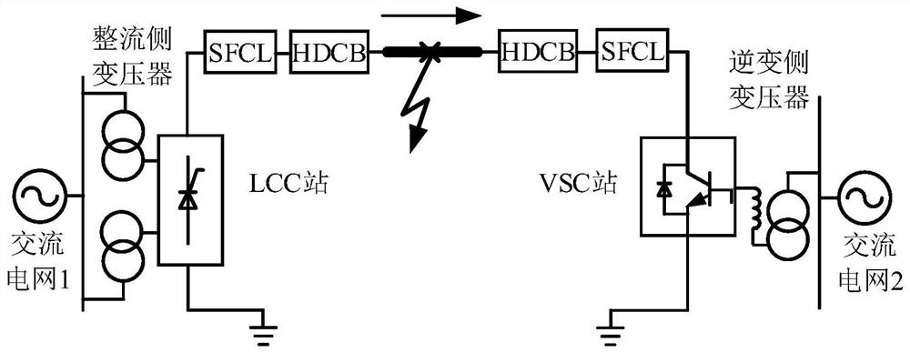
[0070] Example 1: The fault start time is t 0 = 3s, the fault location is set at the midpoint of the DC transmission line, the fault resistance (also called transition resistance) is set to 1Ω, and the fault duration is 250ms. The resistance R of the resistive superconducting current limiter on the inverter side SC-VSC Set to 0Ω (no SFCL), 20Ω, 30Ω, 40Ω, 50Ω, and the resistance R of the resistive superconducting current limiter on the rectification side SC-LCC remain unchanged at 50Ω. The fault current response obtained at the LCC converter station and the VSC converter station is shown in Figure 9(a) and Figure 9(b), and the transient voltage of the hybrid DC circuit breaker at the side of the LCC converter station and the VSC converter station The responses are shown in Figure 10(a) and Figure 10(b). The response data of VSC converter station side is shown in attached table 2.
[0071] Attached Table 2 VSC converter station side fault response data when changing the SFCL...
example 2
[0073] Example 2: The fault start time is t 0 = 3s, the fault location is set at the midpoint of the DC transmission line, the fault resistance (also called transition resistance) is set to 1Ω, and the fault duration is 250ms. The resistance R of the resistive superconducting current limiter on the inverter side SC-VSC Set to 30Ω, the resistance R of the rectification side resistive superconducting current limiter SC-LCC Set to 50Ω, the delay time T of the main circuit breaker d The settings are 3ms, 4ms, 5ms, 6ms, 7ms. The fault current responses obtained at the LCC converter station and VSC converter station are shown in Figure 11(a) and Figure 11(b), and the transient voltage of the hybrid DC circuit breaker at the LCC converter station and VSC The responses are shown in Figure 12(a) and Figure 12(b). The response data at the VSC converter station side is shown in Attached Table 3.
[0074] Attached Table 3 VSC Converter Station Side Fault Response Data When Changing t...
PUM
 Abstract
Description
Claims
Application Information
 - R&D
- Intellectual Property
- Life Sciences
- Materials
- Tech Scout
- Unparalleled Data Quality
- Higher Quality Content
- 60% Fewer Hallucinations
Browse by: Latest US Patents, China's latest patents, Technical Efficacy Thesaurus, Application Domain, Technology Topic, Popular Technical Reports.
© 2025 PatSnap. All rights reserved.Legal|Privacy policy|Modern Slavery Act Transparency Statement|Sitemap|About US| Contact US: help@patsnap.com


