
Anti-floating reinforcement structure of in-operation subway tunnel and construction method

A technology for strengthening structures and construction methods, applied in tunnels, tunnel linings, underground chambers, etc., can solve the problems of insufficient bearing capacity of anti-floating reinforcement construction structures for operating subway tunnels and weak construction integrity.

Pending Publication Date: 2020-02-25
杭州合跃科技有限责任公司 +1
View PDF0 Cites 4 Cited by
  • Summary
  • Abstract
  • Description
  • Claims
  • Application Information

AI Technical Summary

Problems solved by technology

[0006] The purpose of the present invention is to solve the deficiencies such as the lack of effective measures in the prior art to solve the problem of anti-floating reinforcement of subway tunnels in operation, insufficient bearing capacity of construction structures, and weak construction integrity, and proposes a method for anti-floating and reinforcement of subway tunnels in operation Combination, simple steps, reasonable design and simple construction, good construction structure integrity, suitable for the anti-floating reinforcement structure and construction method of subway tunnel construction during the subway outage window period

Method used


Image

  • Anti-floating reinforcement structure of in-operation subway tunnel and construction method
  • Anti-floating reinforcement structure of in-operation subway tunnel and construction method
  • Anti-floating reinforcement structure of in-operation subway tunnel and construction method

Examples


Embodiment 1

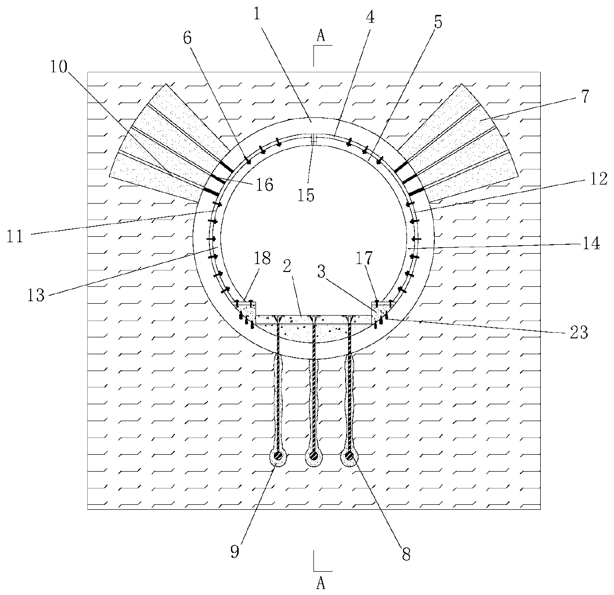
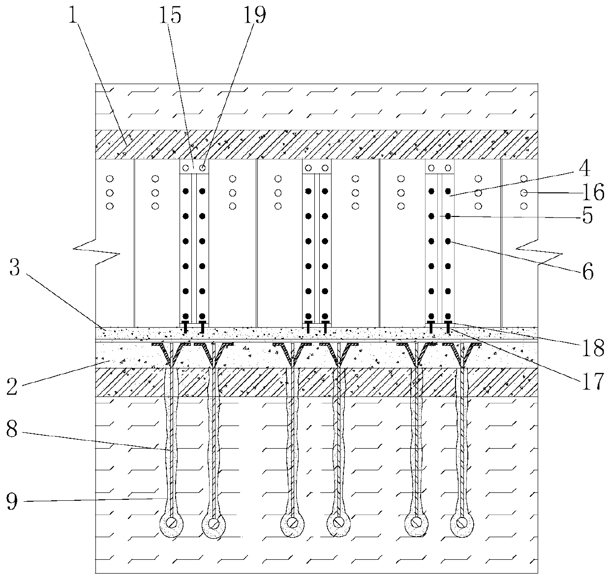
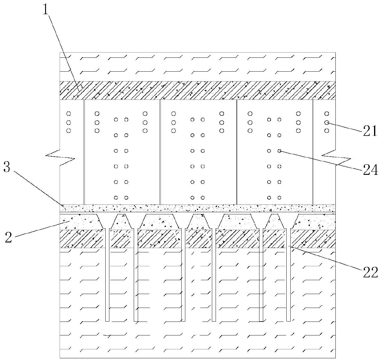
[0084] combined with Figure 1~4 As shown, the present invention relates to an anti-floating reinforcement structure of subway tunnels in operation, which is used to solve the problem of tunnel floating caused by rising water level or unloading above the tunnel. The structure includes tunnel lining 1, and tunnel lining 1 is equipped with The ballast bed 2 and the inner reinforcement structure, the outer reinforcement structure and the anti-floating structure are provided on the outside of the tunnel lining 1, and caps 3 are provided on both sides of the ballast bed 2, and the caps 3 are connected to the tunnel lining 1 through a number of expansion bolts 23.

[0085] combined with Figure 1~4 As shown, the internal reinforcement structure includes steel ferrules 4 and stiffeners 5 arranged at intervals, the stiffeners 5 are welded to the steel ferrules 4, the steel ferrules 4 include left arc-shaped steel plates 11 and right arc-shaped steel plates 12, and the stiffeners The ...

Embodiment 2

[0089] When the operating subway tunnel is raised due to rising water level, the following steps shall be adopted for construction:

[0090] 1) According to the construction environment such as the limit of the operating line, the minimum radius of the line, and the maximum slope, select the manipulator and flatbed truck for construction; etc., to provide an effective site for construction; then cut and chisel the ballast bed 2 and water ditches on both sides of the subway track until the shield segment is exposed, and after cutting, the side of the ballast bed 2 is roughened, and, using The high-pressure water gun cleans the surface of the tunnel lining 1, and treats loose objects such as collapse and calcification on the surface of the segment.

[0091] 2) Construction cap 3 at the position where the ballast bed is cut and chiseled on both sides of the subway track: according to the cutting size of the ballast bed 2, the cap 3 is processed on site, transported to the site by...

Embodiment 3

[0128] When the operating subway tunnel is lifted due to the unloading above the tunnel, the following steps shall be adopted for construction:

[0129] 1) According to the construction environment such as the limit of the operating line, the minimum radius of the line, and the maximum slope, select the manipulator and flatbed truck for construction; etc., to provide an effective site for construction; then cut and chisel the ballast bed 2 and water ditches on both sides of the subway track until the shield segment is exposed, and after cutting, the side of the ballast bed 2 is roughened, and, using The high-pressure water gun cleans the surface of the tunnel lining 1, and treats loose objects such as collapse and calcification on the surface of the segment.

[0130] 2) Construction cap 3 at the position where the ballast bed is cut and chiseled on both sides of the subway track: according to the cutting size of the ballast bed 2, the cap 3 is processed on site, transported to...


PUM


Abstract

The invention relates to an anti-floating reinforcement structure of an in-operation subway tunnel and a construction method. The anti-floating reinforcement structure is characterized in that an internal reinforcement structure is arranged inside a tunnel lining, and an external reinforcement structure and an anti-floating structure are arranged outside the tunnel lining; the internal reinforcement structure includes a steel ferrule and a stiffening plate which are arranged in a spaced manner, the stiffening plate and the steel ferrule are welded, and the steel ferrule is fixed to the tunnellining through wall-hanging expansion bolts; the external reinforcement structure includes grouting reinforcement soil bodies, and the grouting reinforcement soil bodies are symmetrically arranged onthe slightly upper portions of the tunnel lining; and the anti-floating structure includes anchor rods, the anchor rods are arranged at the bottom of the tunnel lining, the top ends of the anchor rodsare anchored inside a track bed, and grouting bodies are arranged at the around the positions, below the tunnel lining, of the anchor rods. By means of the anti-floating reinforcement structure, influences of the surrounding soil disturbance on the subway tunnel can be reduced, the anti-floating performance of the subway tunnel and the stiffness of the tunnel are increased, and the floating amount of the tunnel and the fracture surface deformation amount are reduced when the groundwater level rises or covering soil bodies of the tunnel are excavated.

Description

technical field [0001] The invention relates to the field of anti-floating technology of subway tunnels, in particular to an anti-floating reinforcement structure and construction method of subway tunnels in operation. Background technique [0002] With the increasing traffic flow, the traffic pressure on the surface roads is gradually intensifying. As a result, the development and construction of underground space is also setting off a climax all over the country. The urban underpass tunnel separates the cross-traffic flow in space, improves the traffic comfort, and greatly Alleviate the urban traffic pressure. During the operation phase of the subway, due to changes in the groundwater level or surrounding construction activities, the shield tunnel will rise, and the rise of the segment will have a negative impact on the train's running speed, operating safety, and passenger comfort. [0003] As an important lifeline of urban traffic, the subway tunnel has extremely strict...

Claims


Application Information

Patent Timeline
IPC IPC(8): E21D11/10E21D11/08E21D11/38E21D21/00E21D20/02
CPCE21D11/003E21D11/08E21D11/105E21D11/38E21D20/021E21D21/0026
Inventor 俞国骅丁智李栋樑
Owner 杭州合跃科技有限责任公司
Learn More