Full-fabricated floor slab assembled-type steel-concrete combined floor

A concrete and prefabricated technology, applied in the direction of floor slab, climate change adaptation, building components, etc., can solve the problems of cost waste, insufficient construction speed, large workload, etc., to ensure shear stiffness and bearing capacity, avoid aesthetics, The effect of high installation speed

Pending Publication Date: 2020-02-28
CENT RES INST OF BUILDING & CONSTR CO LTD MCC GRP
View PDF0 Cites 13 Cited by
  • Summary
  • Abstract
  • Description
  • Claims
  • Application Information

AI Technical Summary

Problems solved by technology

[0003] The traditional steel-cast-in-place concrete floor has good mechanical performance and economy, but the cast-in-place floor slab faces the disadvantages of on-site formwork, steel bars and concrete pouring, and the construction is not fast enough, and it does not meet the requirements of building industrialization and green environmental protection. Development concept
In order to meet the needs of industrialized construction, the current floor forms of steel-concrete composite floors mainly include traditional truss-reinforced floor slabs, detachable bottom formwork truss-reinforced floor slabs, and laminated slab composite floors. However, after market verification, these products are all Not yet a mature floor slab solution for residential buildings
The traditional truss-reinforced floor deck has low consumer acceptance due to the exposed profiled steel plate; the construction process of the truss-bar floor deck with removable bottom form is complicated, the actual reusability of the bottom form is not high, and the cost waste is relatively high. Large; while the laminated slab composite floor requires an actual slab thickness greater than 150mm, which is not applicable in residential buildings where the slab thickness is generally 100-120mm

Method used


Image

  • Full-fabricated floor slab assembled-type steel-concrete combined floor
  • Full-fabricated floor slab assembled-type steel-concrete combined floor
  • Full-fabricated floor slab assembled-type steel-concrete combined floor

Examples


Embodiment 1

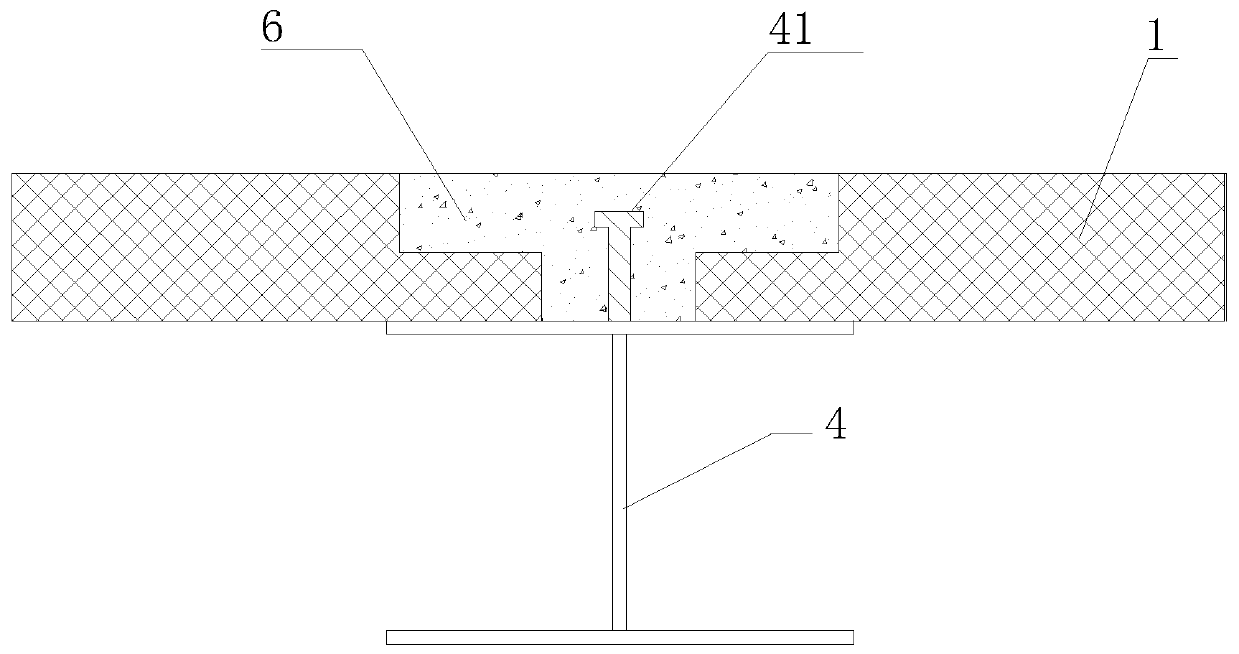
[0031] Such as figure 1 As shown, the fully prefabricated floor slab fabricated steel-concrete composite floor cover of this embodiment includes a beam 4 and a floor slab 1 arranged on the beam. The joint between two adjacent floor slabs is located on the beam, and the floor slab is on the beam. The cross section of the joint is step-shaped, and a plurality of T-shaped connecting nails 41 are arranged in the middle of the beam; concrete 6 is poured at the steps of the two floor slabs, and the concrete connects the two floor slabs and T-shaped connecting nails are connected in one piece.

[0032] Wherein, the height of the T-shaped connecting nail is 2 / 3 of the height of the floor;

Embodiment 2

[0034] This embodiment is a further improvement of embodiment 1, such as Figure 4 to Figure 6 As shown, the upper surface of the floor 1 is provided with reinforcing steel bars 71; the reinforcing steel bars 71 between the two floor slabs are connected by lap steel bars; V-shaped grooves 8 are correspondingly provided on the stage parts of the two floor slabs 1. , Shear ribs 73 are embedded in the V-shaped groove 8.

Embodiment 3

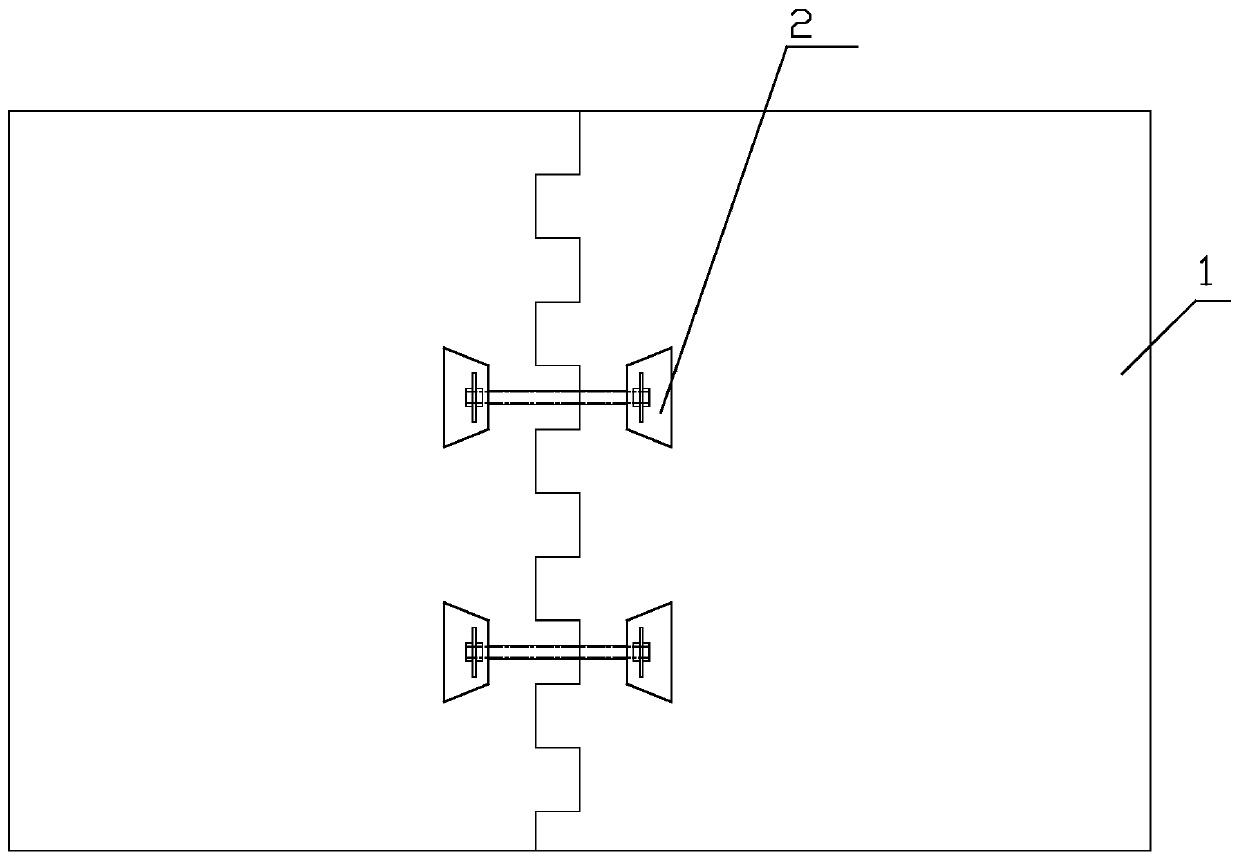
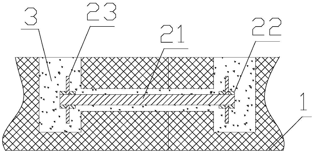
[0036] Such as figure 2 image 3 As shown, the floor slab in this embodiment is a fully prefabricated floor slab, which is formed by splicing two prefabricated floor slabs 1, wherein the joint of the two prefabricated floor slabs has a tooth groove structure, and the two prefabricated floor slabs mesh with each other through the tooth grooves; There are two or more connecting fixtures 2 between the two prefabricated floor slabs, and the connecting fixtures are connected in the following manner:

[0037] A connecting hole is provided at the corresponding position of each prefabricated floor joint;

[0038] An opening slot is provided at the position corresponding to the communicating hole at the splice of each prefabricated floor slab, and the other end of the communicating hole is located in the opening slot; figure 1 As shown, the shape of the open slot is trapezoidal.

[0039] A connecting piece 21 passes through the connecting hole to connect two prefabricated floor slabs;

[0040...


PUM


Abstract

The invention discloses a full-fabricated floor slab assembled-type steel-concrete combined floor. The floor comprises an H-shaped steel beam and floor slabs which are disposed on the beam. One or more rows of connection studs or other connectors are disposed on the H-shaped steel beam; the two adjacent floor slabs in the steel beam-floor slab connection position are placed on the two sides of theupper flange of the steel beam; the sections, in the joint connection position on the beam, of the floor slabs are in a step shape; V-shaped notches are formed in the lower portions of the steps in the spliced joint connection positions of the floor slabs; shear reinforcements are put in the notches, in the two sides of the spliced joints, of the floor slabs; reinforcements on the upper portionsof the steps in the spliced joint connection positions of the floor slabs extend out, and lap joint reinforcements are placed to be connected with the extend-out reinforcements of the floor slabs on the two sides of the spliced joints; and UHPC or ECC concrete materials fill in the space between the floor slabs on the two sides of the spliced joints and the steel beam. According to the floor, thestud connectors, the V-shaped notches in the floor slabs, the shear reinforcements, the lap joint reinforcement structure and the post-cast UHPC or ECC concrete materials are skillfully utilized, andreliable connection between the floor slabs and the steel beam is formed.

Description

Technical field [0001] The invention relates to the field of construction, in particular to a fully prefabricated floor slab assembly type steel-concrete combined floor. Background technique [0002] Steel structure buildings have the unique advantages of being environmentally friendly, recyclable, and good seismic performance, and have outstanding features such as green buildings and industrialization during their full life cycle. Fabricated steel structure buildings will have great development prospects. Residential buildings account for a large proportion of the total construction. At present, steel structure houses in my country account for less than 1%. From the perspective of breaking through the bottleneck of the development of prefabricated steel structures, housing is one of the most important parts of the incremental market. [0003] The traditional steel-in-situ concrete floor slab has good mechanical performance and economy, but the cast-in-situ floor slab is faced wit...

Claims


Application Information

Patent Timeline
Patent Type & Authority Applications(China)
IPC IPC(8): E04B5/02E04B5/10
CPCE04B5/023E04B5/10Y02A30/30
Inventor 刘晓刚曾滨郑明召岳清瑞王月栋王杰李相杰
Owner CENT RES INST OF BUILDING & CONSTR CO LTD MCC GRP
Why Eureka
Try Eureka