Assembled pressure self-balancing magneto-rheological damper

A magneto-rheological damper and self-balancing technology, applied in shock absorbers, shock absorbers, springs/shock absorbers, etc., can solve the problems of damping medium leakage, damper pressure seal failure, damper damage, etc., to achieve Large range of pressure adjustment, sensitive pressure adjustment, and the effect of reducing production costs

Inactive Publication Date: 2020-02-28
南通装配式建筑与智能结构研究院 +1
View PDF0 Cites 1 Cited by
  • Summary
  • Abstract
  • Description
  • Claims
  • Application Information

AI Technical Summary

Problems solved by technology

[0003] In the actual application of magnetorheological dampers, the load conditions in disasters such as earthquakes or strong winds often exceed the theoretical output range of the product. Under extreme disaster conditions, excessive output of magnetorheological dampers may cause damping Damage to the damper or damage to the connecting parts; at the same time, excessive internal pressure of the damper will also increase the risk of seal failure and damping medium leakage
[0004] On the other hand, there are many specifications of the existing magneto-rheological dampers, and the large damper design is not conducive to the streamlined production and storage of the important parts (pistons, piston rods, coils, etc.) of the damper, which also leads to It is noted that magnetorheological dampers are mostly produced by receiving projects. Under the condition of tight production cycle, it is not conducive to the deployment of damper production personnel and the saving of production time and cost; and when the damper is damaged by fatigue or man-made damage, Often because the internal structure of the damper is difficult to disassemble, the entire product is often replaced directly without considering the replacement of important parts, resulting in an increase in cost

Method used


Image

  • Assembled pressure self-balancing magneto-rheological damper
  • Assembled pressure self-balancing magneto-rheological damper
  • Assembled pressure self-balancing magneto-rheological damper

Examples


Embodiment Construction

[0029] The following will clearly and completely describe the technical solutions in the embodiments of the present invention with reference to the accompanying drawings in the embodiments of the present invention. Obviously, the described embodiments are only some, not all, embodiments of the present invention. Based on the embodiments of the present invention, all other embodiments obtained by persons of ordinary skill in the art without making creative efforts belong to the protection scope of the present invention.

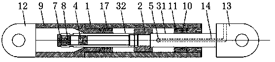
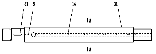
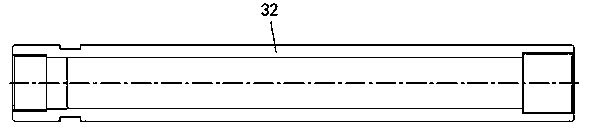
[0030] see Figure 1-5 , the present invention provides a technical solution: an assembled pressure self-balancing magnetorheological damper, which is characterized in that it includes a master cylinder 1, a master piston 2 and a piston rod assembly, and the master piston 2 is placed in the master cylinder 1 Inside, the piston rod assembly passes through the main cylinder 1 and the main piston 2. The main piston 2 divides the main cylinder 1 into two left and ...


PUM


Abstract

The invention discloses an assembled pressure self-balancing magneto-rheological damper. A piston rod adopts a two-section split type structure, a main piston is arranged at the joint of a first piston rod and a second piston rod, the main piston divides a main cylinder barrel into left and right sealing chambers, a magnetorheological damping liquid is filled in the two sealing cavities, a cavityis formed inside the second piston rod, an auxiliary piston inside the cavity divides the cavity inside the second piston rod into two sealed cavities, and the auxiliary piston can freely move along the inner wall of the piston rod under the action of the two sides. On the one hand, the assembled pressure self-balancing magneto-rheological damper can prevent the output of the damper from being toolarge under the extreme working condition while the damping force can be adjusted, and moreover, the damage of the damper itself can be avoided; on the other hand, the energy consumption performanceof the damper can be adjusted by disassembling and replacing the piston, the piston rod and coils, the production cost is effectively reduced, and the industrial production and storage of product parts are facilitated.

Description

technical field [0001] The invention relates to the technical field of construction, in particular to an assembled pressure self-balancing magnetorheological damper. Background technique [0002] The magnetorheological damper is a damper with magnetorheological fluid as the damping medium. It mainly winds an electromagnetic coil on the piston. The magnetic field generated after the coil is energized acts on the magnetorheological fluid, and the viscosity of the damping medium is changed by the magnitude of the current. , so as to provide a changed damping force, which has great application value in the field of vibration control. [0003] In the actual application of magnetorheological dampers, the load conditions in disasters such as earthquakes or strong winds often exceed the theoretical output range of the product. Under extreme disaster conditions, excessive output of magnetorheological dampers may cause damping Damage to the damper or damage to the connecting parts; a...

Claims


Application Information

Patent Timeline
Patent Type & Authority Applications(China)
IPC IPC(8): F16F9/32F16F9/53
CPCF16F9/3221F16F9/535F16F9/537
Inventor 欧进萍白石孔伟明
Owner 南通装配式建筑与智能结构研究院
Why Eureka
Try Eureka