
Method for forming semiconductor

A semiconductor and floating gate technology, applied in the field of semiconductor formation, can solve problems such as crosstalk, slow etching, abnormal reading and writing of arrays, etc., and achieve the effects of reducing deviation, balancing the amount of etching, and improving programming and reading and writing

Pending Publication Date: 2020-02-28
SHANGHAI HUALI MICROELECTRONICS CORP
View PDF3 Cites 2 Cited by
  • Summary
  • Abstract
  • Description
  • Claims
  • Application Information

AI Technical Summary

Problems solved by technology

The wet etching plus dry etching process has the problem that the etching accuracy is greatly affected by the dimensional consistency of the active area, which directly affects the control of key etching accuracy parameters. The specific performance is: small area etching is relatively slower, and faster for large areas
The present invention deeply analyzes the root cause of the fluctuation of the etching precision, which is that the dry etching process is very sensitive to the etched area. During dry etching, the etching rate of small areas is relatively slow, while that of large areas is relatively fast. In the end, the deviation of etching accuracy far exceeds the range of + / -20A, resulting in abnormal reading and writing of the array, crosstalk and other problems

Method used


Image

  • Method for forming semiconductor
  • Method for forming semiconductor
  • Method for forming semiconductor

Examples


Embodiment Construction

[0027] The specific implementation manner of the present invention will be described in more detail below with reference to schematic diagrams. The advantages and features of the present invention will be more apparent from the following description. It should be noted that all the drawings are in a very simplified form and use imprecise scales, and are only used to facilitate and clearly assist the purpose of illustrating the embodiments of the present invention.

[0028] Hereinafter, the terms "first", "second", etc. are used to distinguish between similar elements, and are not necessarily used to describe a specific order or chronological order. It is to be understood that these terms so used are interchangeable under appropriate circumstances. Similarly, if a method described herein includes a series of steps, the order in which these steps are presented is not necessarily the only order in which these steps can be performed, and some described steps may be omitted and / or...


PUM


Abstract

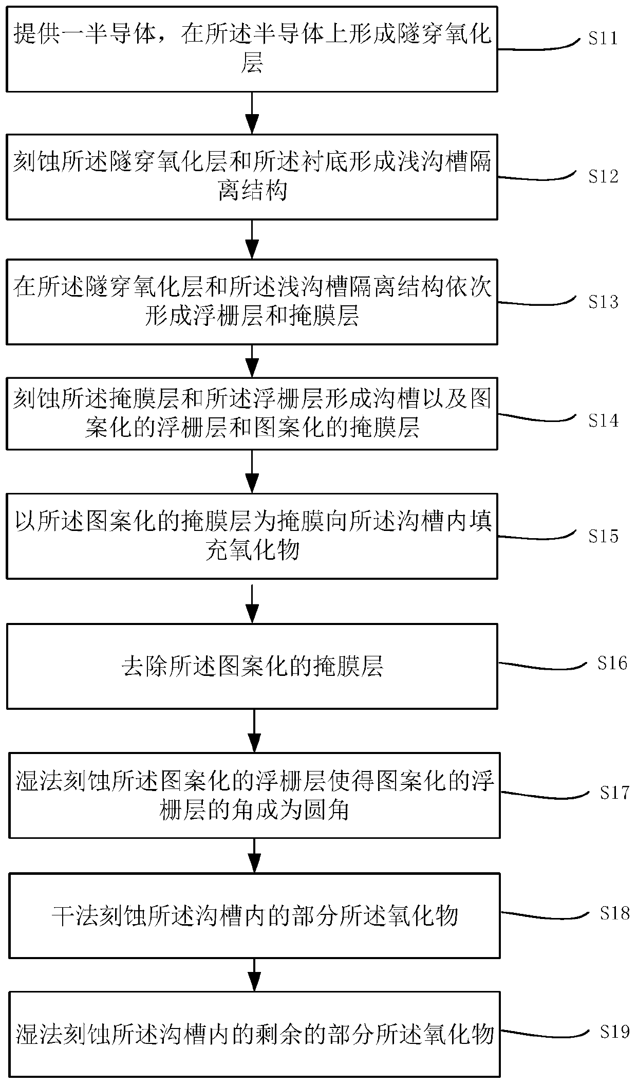
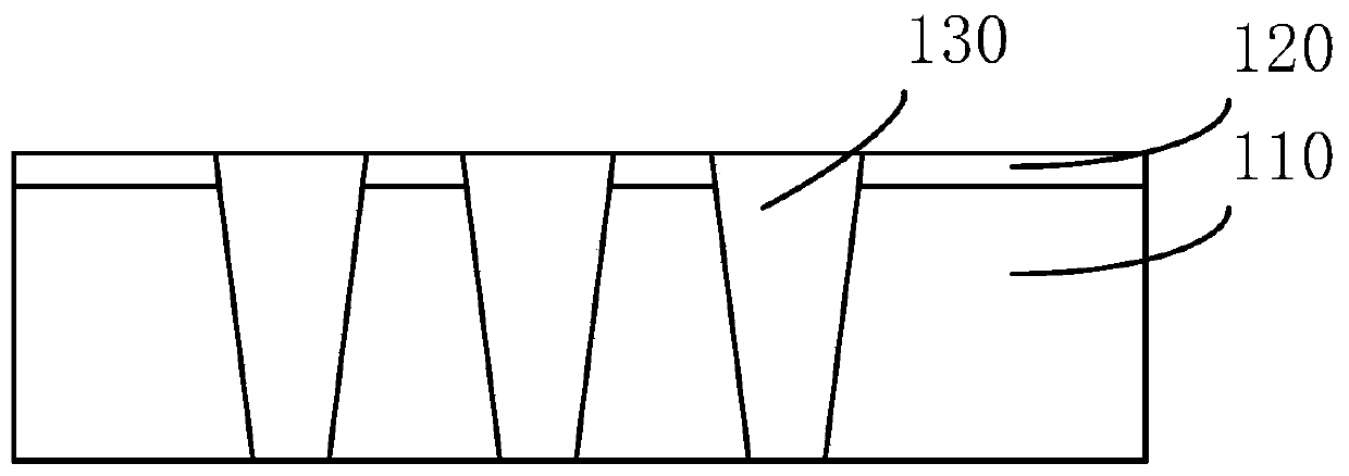
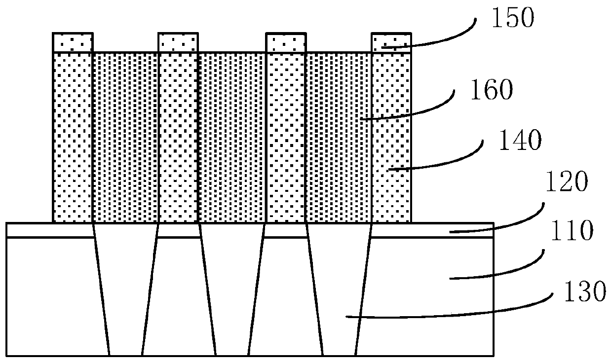
The invention provides a method for forming a semiconductor, which comprises the steps of providing a semiconductor; forming a tunneling oxide layer on the semiconductor; etching the tunneling oxide layer and the substrate to form a shallow trench isolation structure; sequentially forming a floating gate layer and a mask layer on the tunneling oxide layer and the shallow trench isolation structure; etching the mask layer and the floating gate layer to form a trench, a patterned floating gate layer and a patterned mask layer; filling the trench with oxide by taking the patterned mask layer as amask; removing the patterned mask layer; performing wet etching on the patterned floating gate layer to enable corners of the patterned floating gate layer to be rounded; carrying out dry etching onpart of the oxide in the trench; and performing wet etching on the remaining part of the oxide in the trench. According to the method provided by the invention for forming the semiconductor, a methodof carrying out wet etching, drying etching and wet etching is adopted after the right-angled columnar patterned floating gate layer is formed, so that the etching amount can be balanced, the deviation of the etching amount can be reduced, and finally, the programming and reading of a semiconductor device can be improved.

Description

technical field [0001] The invention relates to the technical field of semiconductors, in particular to a method for forming a semiconductor. Background technique [0002] At present, in the 19NAND project, the process of etching the ST I oxide layer on the side of the floating gate is a wet etching plus dry etching process, which realizes the smoothness of the top of the floating gate, consumes part of the side wall of the floating gate, and increases the space. The bottom of the U-shaped groove is smooth to prevent tip discharge. The wet etching plus dry etching process has the problem that the etching accuracy is greatly affected by the dimensional consistency of the active area, which directly affects the control of key etching accuracy parameters. The specific performance is: small area etching is relatively Slower, and faster for large areas. The present invention deeply analyzes the root cause of the fluctuation of the etching precision, which is that the dry etchin...

Claims


Application Information

Patent Timeline
Patent Type & Authority Applications(China)
IPC IPC(8): H01L27/11524H01L21/28H01L21/311H10B41/35
CPCH01L29/401H01L21/31111H10B41/35
Inventor 何理巨晓华王奇伟
Owner SHANGHAI HUALI MICROELECTRONICS CORP
Learn More