Permanent magnet ECR ion source permanent magnet ring mounting structure and processing method thereof

A technology of installation structure and processing method, which is applied in the direction of plasma, ion beam tube, permanent magnet, etc., can solve the problems of lack of magnetic ring and broken permanent magnetic ring, reduction of magnetic field strength, broken magnetic ring, etc., to simplify the assembly process , reduce the possibility, the installation structure is easy to use

Pending Publication Date: 2020-03-06
CHINA INSTITUTE OF ATOMIC ENERGY
View PDF0 Cites 2 Cited by
  • Summary
  • Abstract
  • Description
  • Claims
  • Application Information

AI Technical Summary

Problems solved by technology

[0003] The existing conventional permanent magnet ring is made of NdFeB material, which is characterized by high hardness and fragility. The magnetization remanence of the conventional permanent magnet ring is on the order of T, and the magnetic ring and the iron ring or the magnetic ring and the magnetic ring are close to each other. The magnetic force when the distance is in contact is very large, which will make the assembly between the magnetic ring and the iron ring or between the magnetic ring and the magnetic ring (coaxial installation of the magnetic ring and the magnetic ring or the magnetic ring and the iron ring) difficult, and often occur during the assembly process. Breaking the magnetic ring, and a sudden collision will lead to a decrease in the magnetic field strength, resulting in failure of the experiment or waste of time and economic loss
[0004] The above-mentioned existing technical solutions have the following defects: in the prior art, there is a lack of a permanent magnetic ring installation structure that can prevent the magnetic ring from being smashed and simplify the assembly process of the permanent magnetic ring

Method used


Image

  • Permanent magnet ECR ion source permanent magnet ring mounting structure and processing method thereof
  • Permanent magnet ECR ion source permanent magnet ring mounting structure and processing method thereof
  • Permanent magnet ECR ion source permanent magnet ring mounting structure and processing method thereof

Examples


Embodiment 1

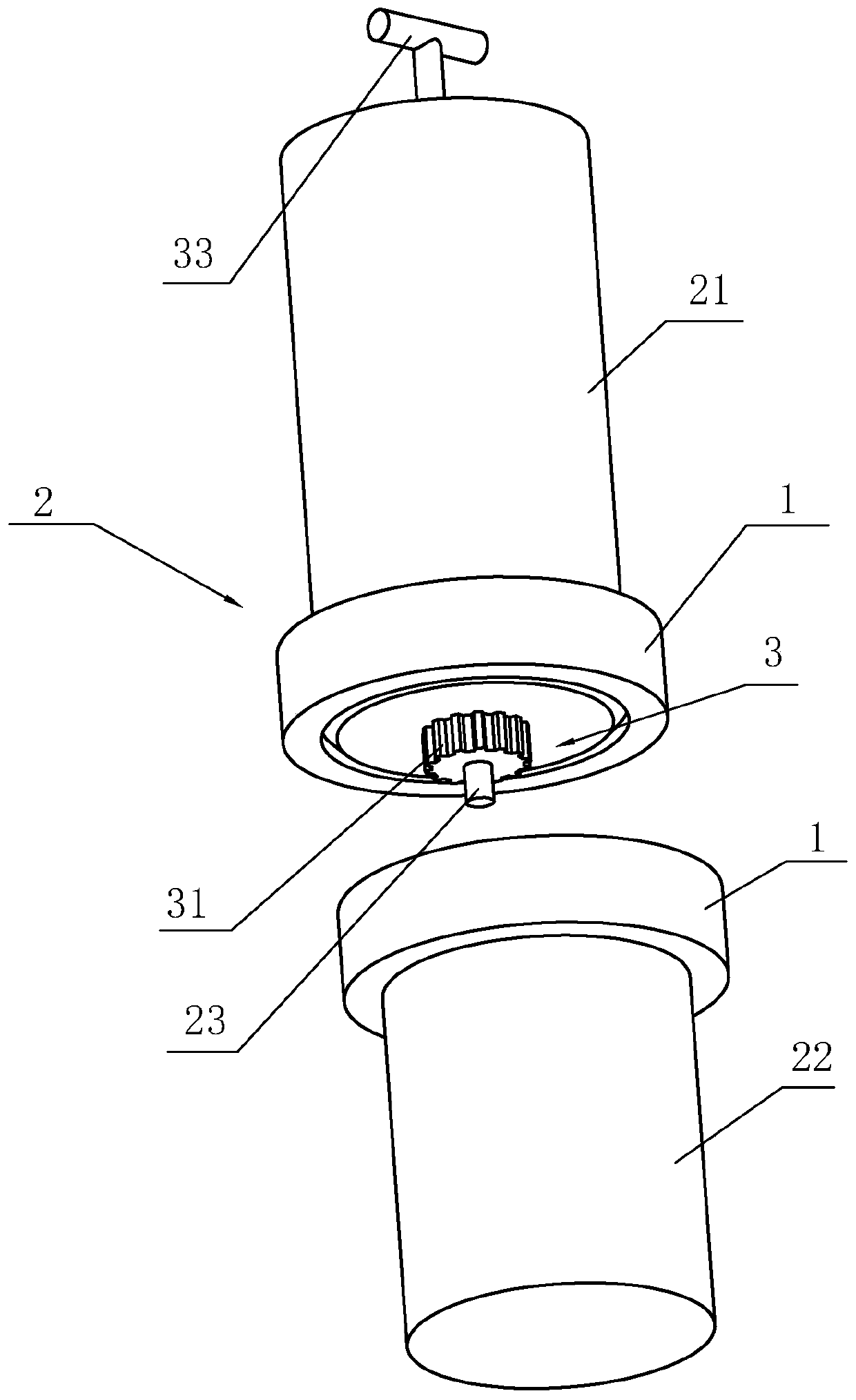
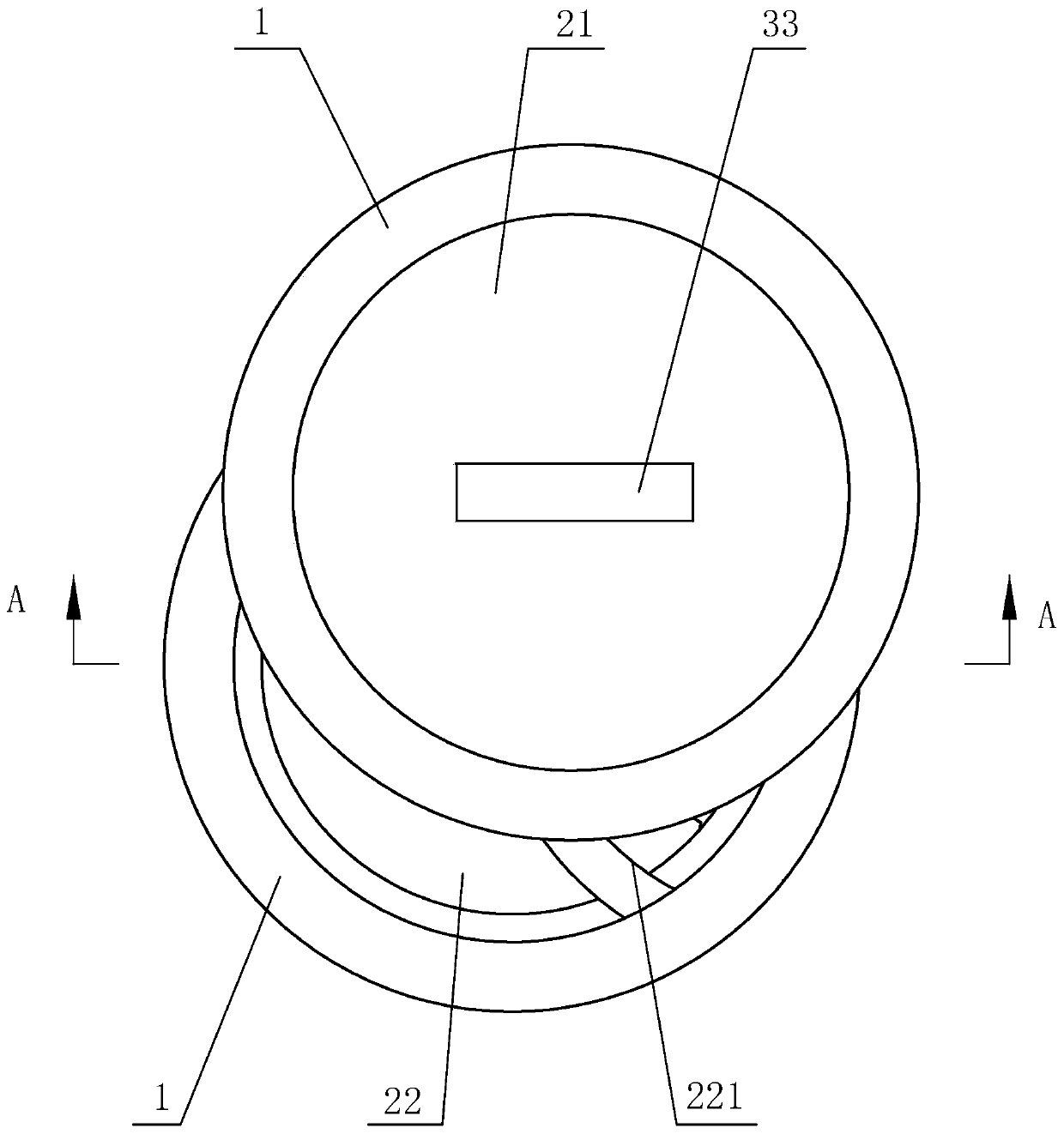
[0041] refer to figure 1 and figure 2, the present invention provides an installation structure of a permanent magnet ECR ion source permanent magnet ring, including a non-magnetic moving bar 21, a static bar 22 and a positioning rod 23, and the outer part of the moving bar 21 and the static bar 22 The diameter is the same as the inner diameter of the permanent magnet ring 1, the positioning rod 23 is arranged at one end of the moving bar 21, the positioning rod 23 is coaxially arranged with the moving bar 21, and an arc-shaped guide passing through the center of the circle is provided on one end of the static bar 22. Groove 221 , the two ends of the guide groove 221 run through the outer surface of the static bar 22 , and the guide groove 221 matches the positioning groove 212 .

[0042] When the permanent magnet ring 1 needs to be assembled, the permanent magnet ring 1 to be assembled is first set on the moving bar 21 and the static bar 22 respectively, and the permanent m...

Embodiment 2

[0051] The invention provides a method for processing the mounting structure of a permanent magnet type ECR ion source permanent magnet ring, comprising the following steps:

[0052] S1, processing two nylon rods with the same outer diameter as the inner diameter of the permanent magnet ring 1 to be installed, the two rods are respectively a moving rod 21 and a static rod 22;

[0053] S2, process the moving bar 21 and the static bar 22:

[0054] S21, mill out the installation hole on the end face of the moving bar 21, then insert the positioning rod 23 made of stainless steel into the installation hole, and the two ends of the positioning rod 23 extend to the outside of the moving bar 21;

[0055] S22. Weld the mounting block 31 with a gear-shaped outer surface on the peripheral surface of the positioning rod 23. The welding position of the mounting block 31 is located outside the moving bar 21. The side of the moving bar 21 away from the mounting block 31 is connected to the ...

Embodiment 3

[0062] refer to Figure 5 , the present invention provides an installation structure of a permanent magnet type ECR ion source permanent magnet ring, comprising a moving bar 21 made of nylon, a static bar 22 made of nylon and a positioning rod 23 made of stainless steel, the moving bar 21 and the static The outer diameter of bar stock 22 is all identical with the inner diameter of permanent magnet ring 1, and positioning rod 23 is arranged on one end of moving bar stock 21, and positioning bar 23 is coaxially arranged with moving bar stock 21, and one end surface of static bar stock 22 is provided with a The arc-shaped guide groove 221 passing through the center of the circle, the two ends of the guide groove 221 run through the outer surface of the static bar 22 , the guide groove 221 matches the positioning groove 212 .

[0063] When the permanent magnet ring 1 needs to be assembled, the permanent magnet ring 1 to be assembled is first set on the moving bar 21 and the static...


PUM


Abstract

The invention relates to the field of permanent magnet type ECR ion sources, and particularly relates to a permanent magnet ECR ion source permanent magnet ring mounting structure and a processing method thereof. The structure comprises a movable bar material and a static bar material which are both made of non-magnetic materials and have the same inner diameter as a permanent magnet ring to be installed; a positioning rod coaxial with the movable bar material is arranged at one end of the movable bar material, an arc-shaped guide groove allowing the positioning rod to slide is formed in the end face of the static bar material and the guide groove passes through the axis of the static bar material so that the effects of simplifying the assembling process of the permanent magnet ring, saving time and labor and reducing the possibility that the magnetic ring is crushed are achieved.

Description

technical field [0001] The invention relates to the field of permanent magnet ECR ion sources, in particular to an installation structure of a permanent magnet ring of a permanent magnet ECR ion source and a processing method thereof. Background technique [0002] Currently in the field of permanent magnet ECR ion sources, the electron cyclotron resonance magnetic field is provided by a permanent magnet ring and a magnetically conductive iron ring or a permanent magnet ring and a permanent magnet ring. [0003] The existing conventional permanent magnet ring is made of NdFeB material, which is characterized by high hardness and fragility. The magnetization remanence of the conventional permanent magnet ring is at the T level. The magnetic force when the distance is in contact is very large, which will make the assembly between the magnetic ring and the iron ring or between the magnetic ring and the magnetic ring (coaxial installation of the magnetic ring and the magnetic rin...

Claims


Application Information

Patent Timeline
Patent Type & Authority Applications(China)
IPC IPC(8): H05H1/46H01J27/18H01F7/02
CPCH01F7/0273H01J27/18H05H1/46
Inventor 张贺贾先禄郑侠王景峰
Owner CHINA INSTITUTE OF ATOMIC ENERGY
Why Eureka
Try Eureka