Coated cutting tool

A cutting tool and coating technology, which is applied in the direction of manufacturing tools, workpieces, turning equipment, etc., can solve the problems of inability to prolong tool life, and achieve the effects of prolonging tool life, excellent wear resistance and defect resistance

Active Publication Date: 2020-03-10
TUNGALOY CORP
View PDF7 Cites 2 Cited by
  • Summary
  • Abstract
  • Description
  • Claims
  • Application Information

AI Technical Summary

Problems solved by technology

This leads to the problem that the life of the tool cannot be extended

Method used


Image

  • Coated cutting tool
  • Coated cutting tool
  • Coated cutting tool

Examples


Embodiment

[0088] Hereinafter, the present invention will be explained in more detail through examples, but the present invention is not limited to these examples.

[0089] As a base material, it is prepared to be processed into the blade shape of CNMG120412 and has 87.0WC-8.6Co-2.0TiN-2.0NbC-0.4Cr 3 C 2 (The above is a cemented carbide with a composition of mass %). After rounding the ridgeline portion of the tip of the base material with a SiC brush, the surface of the base material is cleaned.

[0090] [Invention products 1-11 and comparative products 1-9]

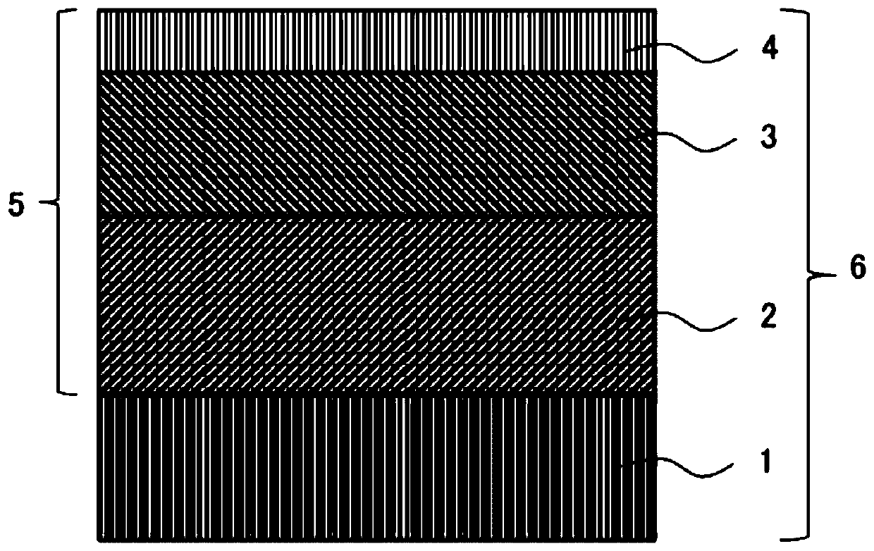
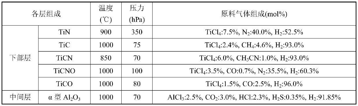
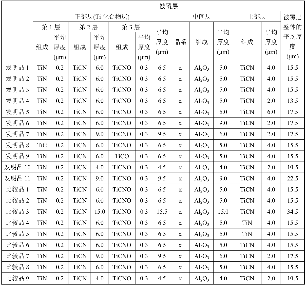
[0091] After cleaning the surface of the substrate, a coating layer is formed by a chemical vapor deposition method. First, the substrate is placed in an external thermal chemical vapor deposition apparatus, and under the conditions of the composition, temperature and pressure of the source gas shown in Table 1, the first layer, the second layer, and the third layer The order of and the average thickness shown in Table 2 form the lower...


PUM

PropertyMeasurementUnit
thicknessaaaaaaaaaa
thicknessaaaaaaaaaa
thicknessaaaaaaaaaa

Abstract

An object of the present invention is to provide a coated cutting tool which has excellent wear resistance and fracture resistance and which accordingly allows for an extended tool life. The inventionrelates to a coated cutting tool comprising a substrate and a coating layer formed on a surface of the substrate, wherein: the coating layer comprises a lower layer, an intermediate layer and an upper layer, the lower layer, the intermediate layer and the upper layer being laminated in order from the substrate side toward a surface side of the coating layer; the lower layer comprises one Ti compound layer or two or more Ti compound layers; the intermediate layer contains alpha-Al2O3; the upper layer contains TiCN; an average thickness of the lower layer is from 4.0 [mu]m or more to 10.0 [mu]mor less; an average thickness of the intermediate layer is from 3.0 [mu]m or more to 10.0 [mu]m or less; an average thickness of the upper layer is from 1.5 [mu]m or more to 6.5 [mu]m or less; a ratio of a length of sigma3 grain boundaries to a total 100% length of all grain boundaries in a specific region of the upper layer is from 20% or more to 60% or less; and a ratio of (111)-oriented grainsin the upper layer is 30 area% or more.

Description

Technical field [0001] The present invention relates to a coated cutting tool. Background technique [0002] In the past, coated cutting tools made by vapor-depositing a coating layer with a total film thickness of 3-20 μm on the surface of a substrate made of cemented carbide by chemical vapor deposition were used for cutting steel, cast iron, etc. The technology is widely known. As the above-mentioned coating layer, for example, a single layer or a single layer consisting of one selected from the group consisting of Ti carbides, nitrides, carbonitrides, oxycarbides and oxycarbonitrides, and alumina is known. A coating layer composed of two or more layers. [0003] For example, Patent Document 1 discloses a coated cutting tool, which is characterized in that the coated cutting tool is composed of a base material of cemented carbide, cermet, ceramic, steel or cubic boron nitride, and a total coating film A multi-layer wear-resistant coating with a thickness of 5 to 25 μm and con...

Claims


Application Information

Patent Timeline
Patent Type & Authority Applications(China)
IPC IPC(8): B23B27/00
CPCB23B27/00B23B2222/16B23B2222/28B23B2222/88B23B2224/36B23B2226/12B23B2226/18B23B2228/04B23B2228/08B23B2228/36C23C16/0227C23C16/0254C23C16/0272C23C16/36C23C16/403C23C28/04C23C28/042C23C28/044C23C30/005B23B27/148B23B2228/105
Inventor 福岛直幸
Owner TUNGALOY CORP
Why Eureka
Try Eureka