Crankshaft and inverter compressor

A frequency conversion compressor and crankshaft technology, applied in the field of compressors, can solve problems affecting the normal operation of compressors, oil leakage accidents, and low strength of the main shaft

Pending Publication Date: 2020-03-10
ANHUI MEIZHI COMPRESSOR
View PDF0 Cites 0 Cited by
  • Summary
  • Abstract
  • Description
  • Claims
  • Application Information

AI Technical Summary

Problems solved by technology

From the above formula of oil pump head, it can be seen that the oil pump head is positively correlated with the angular velocity ω, so the oil pumping capacity of the variable frequency compressor is poor when the speed is low, and there is a problem of poor lubrication caused by insufficient oil supply, which affects the normal operation of the compressor
In order to ensure the amount of oil, the maximum radius R can be increased by reducing the wall thickness of the spindle. The first solution: increase the radius of the oil inlet passage (spindle oil passage) in the spindle as a whole, so that the wall thickness of the spindle decreases as a whole , the strength of the main shaft will not meet the needs of normal work. For example, the oil pump parts are installed at the end of the main shaft away from the crank arm, and there are certain requirements on the wall thickness of the main shaft. ;The second solution: set the main shaft oil channel eccentrically (that is, the main shaft oil channel moves a certain distance radially towards the first oil hole), so that the wall thickness of the main shaft is thinner on one side and thicker on the other side, which will also cause the overall strength of the main shaft to be weaker. Low

Method used


Image

  • Crankshaft and inverter compressor
  • Crankshaft and inverter compressor
  • Crankshaft and inverter compressor

Examples


Embodiment approach

[0040] first implementation

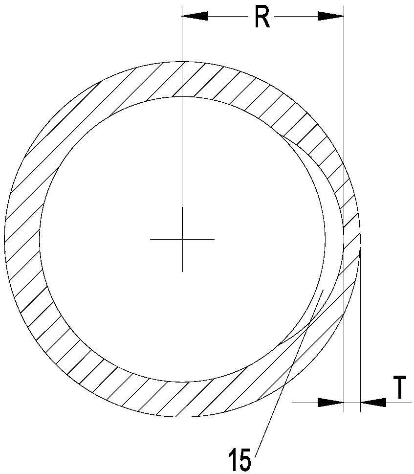
[0041] like image 3 As shown, the cross-section of the second shaft section Z2 is circular, and the cross-section of the recess 15 has a depth in the radial direction from the center (of the cross-section) to two sides (of the cross-section) in the circumferential direction. An arc-shaped structure with gradually smaller sides. Here, the "radial direction" refers to the radial direction of the main shaft 1, and the "circumferential direction" refers to the circumferential direction of the main shaft 1. Further preferably, the cross section of the recessed portion 15 can be an arc-shaped structure formed on the inner wall of the main shaft 1 after the inner circle of the circular ring is moved a set distance in the radial direction toward the first oil through hole 13 . Moreover, the deepest middle position of the arc structure can be aligned and connected with the first oil through hole 13, so that the pump oil lift at the first oil through hol...


PUM


Abstract

The invention relates to the field of compressors, and discloses a crankshaft and an inverter compressor. The crankshaft comprises a main shaft, a crank arm and an auxiliary shaft which are connectedin sequence; and the auxiliary shaft is eccentrically arranged relative to the center line of the main shaft, the main shaft is internally provided with a main shaft oil passage extending in the axialdirection, the center line of the main shaft oil passage coincides with the center line of the main shaft, the outer wall of the main shaft is provided with a groove extending helically in the axialdirection, a first oil passing hole and a second oil passing hole, wherein the two ends of the groove communicate with the main shaft oil passage respectively through the first oil passing hole and the second oil passing hole, the first oil passing hole is arranged away from the crank arm relative to the second oil passing hole, the main shaft comprises a first shaft section used for installing oil pump components, and a second shaft section located between the first shaft section and the first oil passing hole in the axial direction in sequence from the end portion away from the crank arm, and the inner wall of the second shaft section is provided with a concave part communicating with the first oil passing hole and extending in the axial direction. According to the crankshaft and the inverter compressor, on the premise of ensuring the strength of the crankshaft, the wall thickness of the main shaft can be minimized to increase the amount of feeding oil.

Description

technical field [0001] The invention relates to the field of compressors, in particular to a crankshaft and an inverter compressor. Background technique [0002] A typical hermetic refrigeration compressor usually includes upper and lower shells, crankcase, crankshaft, oil pump, connecting rod, piston, piston pin, valve group, motor, refrigeration oil, etc. The refrigeration oil is stored at the bottom of the compressor shell, and the crankshaft includes the main shaft , crank arm and countershaft, the inside of the crankshaft is generally provided with an oil inlet channel, using the centrifugal force when the crankshaft is running and cooperating with the oil pump, the refrigerating machine oil at the bottom of the shell can be transported along the oil inlet channel and led to each friction pair of the compressor for lubrication , in order to reduce the friction loss between the various parts during operation, and the refrigerating machine oil also has a certain cooling e...

Claims


Application Information

Patent Timeline
Patent Type & Authority Applications(China)
IPC IPC(8): F04B39/00F04B39/02
CPCF04B39/0094F04B39/02F04B39/0276
Inventor 黎林孙祥张淼
Owner ANHUI MEIZHI COMPRESSOR
Why Eureka
Try Eureka