A steel bar bending machine device for building construction based on plc control

A technology for steel bar bending and building construction. It is used in manufacturing tools, metal processing, and metal processing equipment. It can solve problems such as poor bending effect, angle deviation, and inaccurate angle, so as to facilitate improvement, reduce bending errors, and weaken vibration. Effect

Inactive Publication Date: 2021-05-25
ZHONGHENG CONSTR GRP
View PDF0 Cites 0 Cited by
  • Summary
  • Abstract
  • Description
  • Claims
  • Application Information

AI Technical Summary

Problems solved by technology

[0003] However, the existing steel bar bending devices can usually only bend steel bars of a certain diameter, and in the process of bending steel bars, there are often many different specifications of steel bars. Due to the different thicknesses of steel bars, most steel bars are bent The device can only bend steel bars of a fixed size, and it cannot bend steel bars that are too thick, and the steel bars that are too thin will cause poor bending effects and inaccurate angles; Usually, multiple sets of rollers are installed at the lower end of the steel bar bending work. Although these rollers can make the steel bar bending device easy to move, it is easy to cause the instability of the workbench when it is used, and it is easy to cause the angle of the steel bar to appear when it is bent. Deviation and other issues

Method used


Image

  • A steel bar bending machine device for building construction based on plc control
  • A steel bar bending machine device for building construction based on plc control
  • A steel bar bending machine device for building construction based on plc control

Examples


Embodiment Construction

[0025] The following will clearly and completely describe the technical solutions in the embodiments of the present invention with reference to the accompanying drawings in the embodiments of the present invention. Obviously, the described embodiments are only some, not all, embodiments of the present invention.

[0026] In describing the present invention, it should be understood that the terms "upper", "lower", "front", "rear", "left", "right", "top", "bottom", "inner", " The orientation or positional relationship indicated by "outside", etc. is based on the orientation or positional relationship shown in the drawings, and is only for the convenience of describing the present invention and simplifying the description, rather than indicating or implying that the referred device or element must have a specific orientation, so as to Specific orientation configurations and operations, therefore, are not to be construed as limitations on the invention.

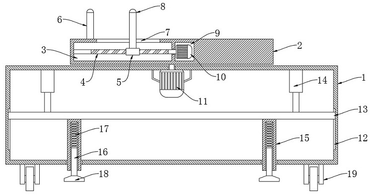
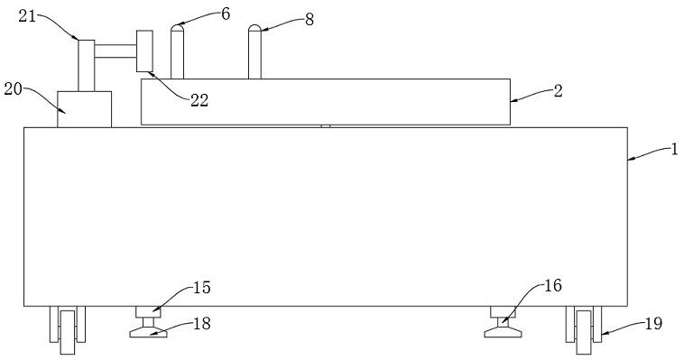
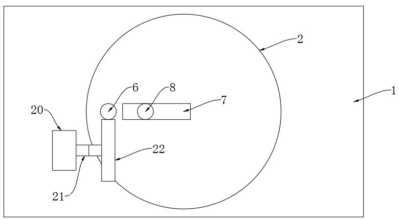
[0027] refer to Figure ...


PUM


Abstract

The invention discloses a steel bar bending machine device for building construction based on PLC control, which includes a hollow workbench and a disc connected to the upper end of the workbench in rotation. The steel bar bending device uses a PLC steel bar bending system. A first motor is fixedly installed on the inner top of the workbench, and the output shaft of the first motor penetrates to the upper end of the workbench and is fixedly connected to the axis of the lower end of the disk. The present invention can control the operation of the electric push rod by setting the stabilizing mechanism and the clamping mechanism, so that the connecting plate pushes the sleeve to move down, so that the supporting rod is pressed downward, and the supporting seat replaces the roller to support the workbench , so that the steel bar bending device is more stable, avoiding the deviation of the steel bar bending angle, and can control the operation of the second motor to adjust the distance between the movable nip roller and the fixed nip roller, so as to clamp and fix the steel bars of different specifications , to meet the bending requirements of steel bars of various thicknesses.

Description

technical field [0001] The invention relates to the technical field of steel bar bending equipment, in particular to a PLC-based steel bar bending machine device for building construction. Background technique [0002] With the continuous development of the social economy, various residential buildings, office buildings, bridges and viaducts have sprung up. These buildings need to use steel bars for steel structure support during the construction process. Before the steel bars are used, a large number of steel bars need to be bent. After it is processed, steel structures such as steel cages meet the needs of use, so mechanical equipment must be used to meet the needs of mass processing. [0003] However, the existing steel bar bending devices can usually only bend steel bars of a certain diameter, and in the process of bending steel bars, there are often many different specifications of steel bars. Due to the different thicknesses of steel bars, most steel bars are bent The...

Claims


Application Information

Patent Timeline
Patent Type & Authority Patents(China)
IPC IPC(8): B21F1/00B21C51/00
CPCB21C51/00B21F1/004
Inventor 张胜军
Owner ZHONGHENG CONSTR GRP
Why Eureka
Try Eureka