
Drill rod structure for down-hole drilling machine

A technology for down-the-hole drilling rigs and drill pipes, which is applied in the direction of drill pipes, drill pipes, drilling equipment, etc., and can solve the problems of difficulty in quickly adjusting the length of drill pipes, easy fatigue damage of drill pipes, and easy entry of fine gravel particles, etc. Achieve the effects of quick adjustment of length, reduction of residue, enhancement of torsion resistance and pressure resistance

Pending Publication Date: 2020-03-17
THE SUNS WORLD JIANGSU OIL & GAS ENG & TECH
View PDF0 Cites 1 Cited by
  • Summary
  • Abstract
  • Description
  • Claims
  • Application Information

AI Technical Summary

Problems solved by technology

[0007] The purpose of the present invention is to provide the drill rod structure for down-the-hole drilling rigs, to solve the problem that the drill rod structure in the above-mentioned background technology is difficult to quickly adjust the length of the drill rod when in use, and rock dust and fine gravel particles are easy to enter the inside of the drill rod and the drill rod. Rods are prone to fatigue damage

Method used


Image

  • Drill rod structure for down-hole drilling machine
  • Drill rod structure for down-hole drilling machine
  • Drill rod structure for down-hole drilling machine

Examples


Embodiment Construction

[0023] The following will clearly and completely describe the technical solutions in the embodiments of the present invention with reference to the accompanying drawings in the embodiments of the present invention. Obviously, the described embodiments are only some, not all, embodiments of the present invention. Based on the embodiments of the present invention, all other embodiments obtained by persons of ordinary skill in the art without making creative efforts belong to the protection scope of the present invention.

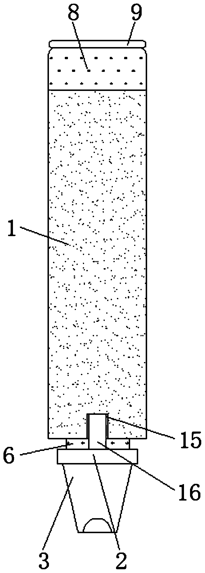
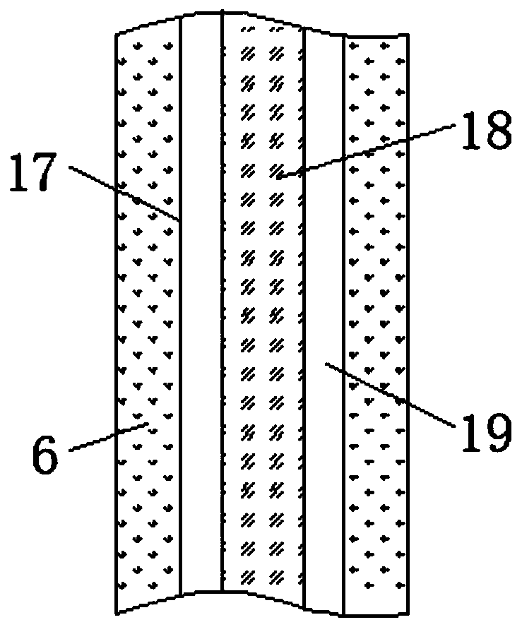
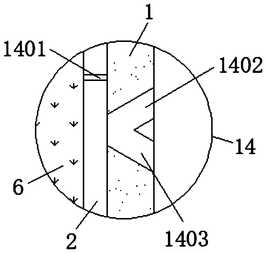
[0024] see Figure 1-4 , an embodiment provided by the present invention: a drill pipe structure for a down-the-hole drilling machine, comprising an outer drill pipe body 1, a telescoping cavity 5, an inner drill pipe body 6, an outer threaded strip 12 and an ash discharge structure 14, and the inner setting of the outer drill pipe body 1 There is a telescopic chamber 5, and the bottom end of the outer drill pipe body 1 below the telescopic chamber 5 is provid...


PUM


Abstract

The invention discloses a drill rod structure for a down-hole drilling machine. The drill rod structure comprises an outer drill rod body, a telescopic cavity, an inner drill rod body, an outer threadbar and an ash discharge structure, wherein the telescopic cavity is formed inside the outer drill rod body, and a through hole is formed in the bottom end, below the telescopic cavity, of the outerdrill rod body; the inner drill rod body is arranged inside the through hole, and the bottom end of the inner drill rod body penetrates through the through hole to be fixed with a connecting block, and a drill bit is fixed to the bottom end of the connecting block; the ash discharging structure is arranged on the inner wall of the bottom of the outer drill rod body, and the top end of the outer drill rod body is fixed with a mounting block; and a sealing ring is fixed at the edge position of the top end of the mounting block, a reinforcing cavity is formed in the inner drill rod body, and an alloy cast iron core is fixed inside the reinforcing cavity. According to the drill rod structure, the quick adjustment function of the length of the drill rod during use can be achieved, the residualof rock dust and fine gravel particulate matter in the drill rod is reduced, and the torsion resistance and the pressure resistance of the drill rod during use are enhanced.

Description

technical field [0001] The invention relates to the technical field of down-the-hole drilling machines, in particular to a drill rod structure for down-the-hole drilling machines. Background technique [0002] The down-the-hole drilling rig is a kind of hole-forming equipment used in mine municipal projects. The down-the-hole drilling rig can drill holes in rocks with medium hardness or above. As an indispensable part of the down-the-hole drilling machine, the drill pipe plays a vital role. [0003] There are a great variety of such drill pipe structures on the market today, which can basically meet people's needs for use, but there are still certain deficiencies, and the specific problems have the following points. [0004] (1) Existing drill rod structures of this type usually need to be replaced with drill rods of different lengths to meet different drilling requirements during use. The steps for replacing drill rods are complicated, time-consuming and labor-intensive, a...

Claims


Application Information

Patent Timeline
Patent Type & Authority Applications(China)
IPC IPC(8): E21B17/00
CPCE21B17/00
Inventor 孙琦
Owner THE SUNS WORLD JIANGSU OIL & GAS ENG & TECH
Learn More