Optical module with fiber winding mechanism

An optical module and optical fiber technology, which is applied in the field of optical communication, can solve the problems of the fiber coiling mechanism occupying the module space, the difficulty in the operation of the coiling process, and the performance impact of the optical module, so as to save internal space, the coiling process is simple and easy, and the operation process Simple and understandable effects

Pending Publication Date: 2020-03-17
HENGTONG ROCKLEY TECHNOLOGY CO LTD +1
View PDF5 Cites 11 Cited by
  • Summary
  • Abstract
  • Description
  • Claims
  • Application Information

AI Technical Summary

Problems solved by technology

If the internal space is insufficient, there will be the following defects: 1. The PCB size is insufficient, and the chips and other heating electronic components are arranged too tightly, which directly leads to poor heat dissipation; 2. Once the high-frequency related chips or circuits are arranged too compactly, they will also It leads to serious internal crosstalk, which greatly reduces the performance of the optical module
[0005] However, the optical fiber has no ductility, and the coiling process is difficult to operate, so it...

Method used


Image

  • Optical module with fiber winding mechanism
  • Optical module with fiber winding mechanism
  • Optical module with fiber winding mechanism

Examples


Embodiment Construction

[0026] The following will clearly and completely describe the technical solutions in the embodiments of the present invention with reference to the drawings in the embodiments of the present invention.

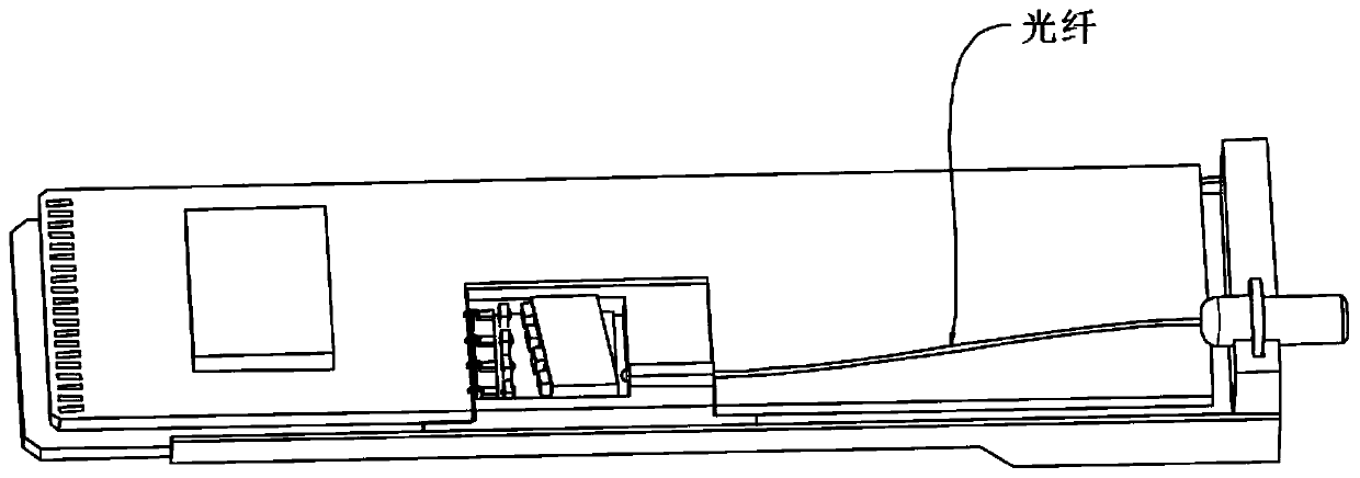
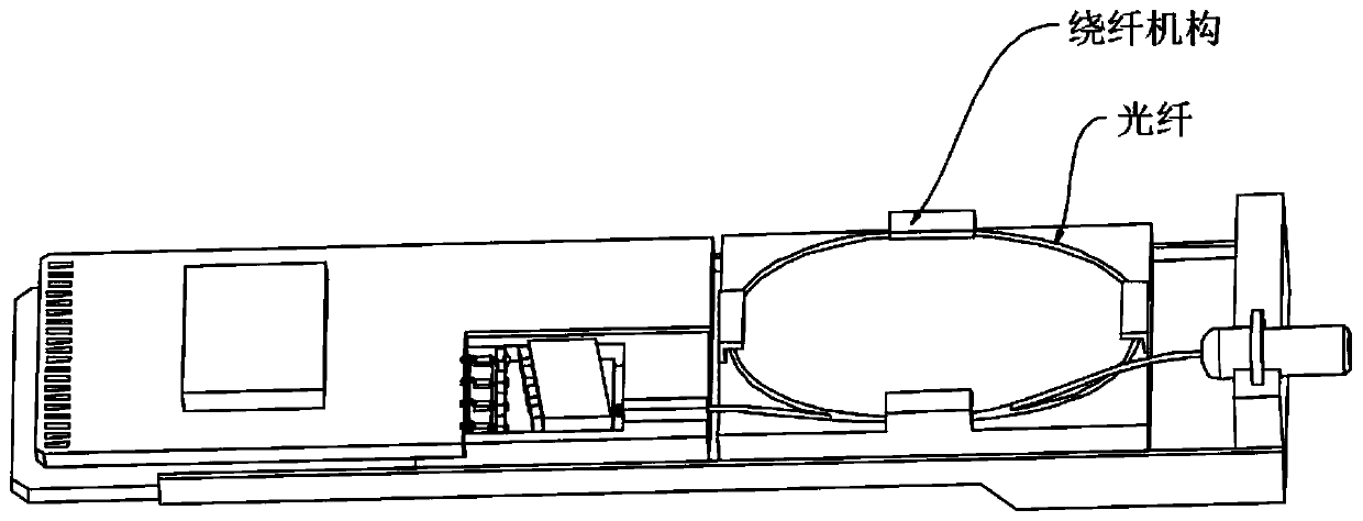
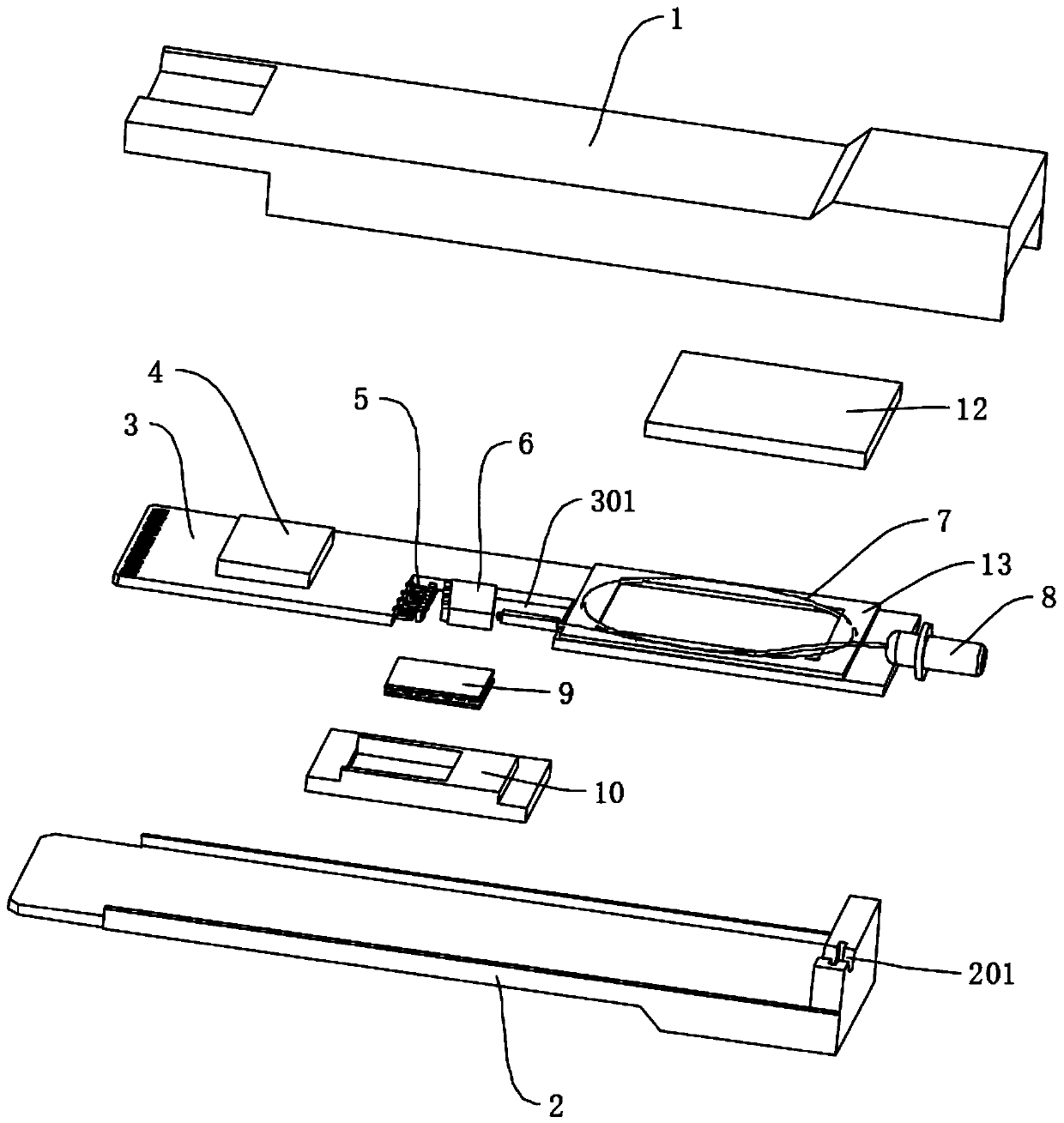
[0027] See Figure 3 to Figure 7 , an optical module with a fiber winding mechanism of the present invention, including an upper heat dissipation housing 1, a lower heat dissipation housing 2 and a PCB circuit board arranged in the upper heat dissipation housing 1 and the lower heat dissipation housing 2, which can be spliced ​​into one 3. The PCB circuit board 3 is provided with a control chip 4, the PCB circuit board 3 is connected to a laser 5 through a bonded gold wire, the front side of the laser 5 is provided with an optical device 6, the optical device 6 is connected to an optical fiber 7, and the other end of the optical fiber 7 The optical head 8 is connected, the laser 5 and the optical device 6 are respectively arranged on the TEC cooler 9, the TEC cooler 9 is insta...


PUM


Abstract

The invention provides an optical module with a fiber winding mechanism. The fiber winding mechanism is simple in structure and extremely simple and convenient to operate so that the fiber coiling process becomes simple and feasible, high subsequent reliability can also be ensured and the internal space occupation of the optical module is greatly reduced. The optical module comprises an upper heatdissipation shell and a lower heat dissipation shell which can be spliced into a whole and a PCB which is arranged in the upper heat dissipation shell and the lower heat dissipation shell. A controlchip is arranged on the PCB, a laser device is connected on the PCB, and an optical device is arranged on the front side of the laser. The optical device is connected with an optical fiber, the otherend of the optical fiber is connected with an optical head, the laser and the optical device are respectively arranged on a TEC refrigerator, the TEC refrigerator is installed in a metal heat sink, and an optical fiber adhesion device is correspondingly arranged on the PCB and located on the rear side of the optical device and used for fixing the coiled optical fiber.

Description

technical field [0001] The invention relates to the technical field of optical communication, in particular to an optical module with a fiber winding mechanism. Background technique [0002] At present, the optical devices and optical ports inside many optical modules are transmitted through optical fibers, but the internal space of optical modules is very limited. Now as the optical module speed is getting higher and higher, the size and number of chips have increased, and the space required inside the optical module is even larger. If the internal space is insufficient, there will be the following defects: 1. The PCB size is insufficient, and the chips and other heating electronic components are arranged too tightly, which directly leads to poor heat dissipation; 2. Once the high-frequency related chips or circuits are arranged too compactly, they will also This leads to serious internal crosstalk, which greatly reduces the performance of the optical module. [0003] At ...

Claims


Application Information

Patent Timeline
IPC IPC(8): G02B6/42G02B6/44
CPCG02B6/4201G02B6/424G02B6/4271G02B6/428G02B6/44
Inventor 梁巍王志勇洪小刚陈奔朱宇
Owner HENGTONG ROCKLEY TECHNOLOGY CO LTD
Why Eureka
Try Eureka