
High-voltage birotor magnetic circuit structure

A dual-rotor, magnetic circuit technology, applied in the magnetic circuit shape/style/structure, magnetic circuit, magnetic circuit rotating parts, etc., can solve the problem that cannot meet the requirements of slender motors, increase rotor structural components, increase rotor failure rate, etc. To achieve the effect of saving permanent magnet materials, increasing output power, and improving magnetic flux utilization

Pending Publication Date: 2020-03-20
日照东方电机有限公司
View PDF1 Cites 0 Cited by
  • Summary
  • Abstract
  • Description
  • Claims
  • Application Information

AI Technical Summary

Problems solved by technology

The permanent magnet magnetic field interacts with the magnetic field generated by the armature winding to generate electromagnetic torque. This dual-rotor structure cannot meet the needs of slender motors
[0004] In view of the above problems, Chinese utility model patent CN201821173356.5 discloses an ultra-slender and high-efficiency permanent magnet synchronous motor for a submersible direct drive pump operated in a downhole barrel, which includes a casing, a stator assembly, a rotor assembly and a rotor shaft; the rotor shaft It is an integral shaft; the rotor assembly includes multiple unit rotors, and the unit rotors include rotor cores and permanent magnets arranged on the rotor cores. Each unit rotor is coaxially connected to the rotor shaft with its rotor cores, and two adjacent units Bearings are arranged between the rotors; the stator assembly includes coil windings, stator silicon steel punches and stator copper punches whose size matches the slot type, the length of the silicon steel core is equal to the length of the rotor core, and the stator copper punches are equal to the width of the bearing , are all fastened on the inner wall of the shell, wherein the unit rotor includes a rotor core and a permanent magnet set on the rotor core, and each unit rotor is coaxially connected to the rotor shaft with its rotor core, and the two adjacent unit rotors There are bearings between them, this structure increases the structural parts of the rotor, increases the difficulty of assembly, and increases the failure rate of the rotor

Method used


Image

  • High-voltage birotor magnetic circuit structure
  • High-voltage birotor magnetic circuit structure
  • High-voltage birotor magnetic circuit structure

Examples


Embodiment 1

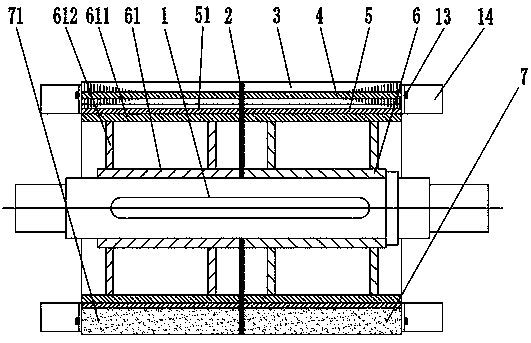
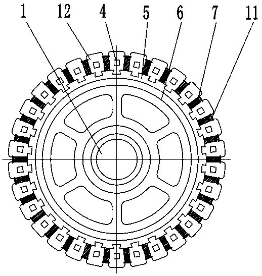
[0034]A high-voltage double-rotor magnetic circuit structure, used for 1000KW, 10KV large-scale high-voltage variable-frequency low-speed high-torque permanent magnet synchronous motors, the length-to-diameter ratio of the rotor is 15, and the outer cylindrical surface of the rotor shaft 1 is provided with right-hand rotation from right to left The sub-support 6, the magnetic isolation spacer 2 and the left rotor support 61, the magnetic isolation spacer 2 is the middle ring in claim 1, the right rotor support 6 and the left rotor support 61 have the same structure, and the left rotor support 61 is the For example, the left rotor bracket outer cylinder 611 is fixed on the outer cylindrical surface sleeved on the rotor shaft 1 through the left rotor bracket web 612, and is restricted from rotating relative to the rotor shaft 1 on the rotor shaft 1 by a flat key. The rotor bracket 6, the magnetic isolation spacer plate 2 and the left rotor bracket 61 are close together, and each ...

Embodiment 2

[0036] A high-voltage dual-rotor magnetic circuit structure, used for 1300KW, 10KV large-scale high-voltage variable-frequency low-speed high-torque permanent magnet synchronous motors, the length-to-diameter ratio of the rotor is 18, and the outer cylindrical surface of the rotor shaft 1 is provided with right-hand rotation from right to left The sub-support 6, the magnetic isolation spacer 2 and the left rotor support 61, the magnetic isolation spacer 2 is the middle ring in claim 1, the right rotor support 6 and the left rotor support 61 have the same structure, and the left rotor support 61 is the For example, the left rotor bracket outer cylinder 611 is fixed on the outer cylindrical surface sleeved on the rotor shaft 1 through the left rotor bracket web 612, and is restricted from rotating relative to the rotor shaft 1 on the rotor shaft 1 by a flat key. The rotor bracket 6, the magnetic isolation spacer plate 2 and the left rotor bracket 61 are close together, and each r...

Embodiment 3

[0038] A high-voltage dual-rotor magnetic circuit structure, used for 900KW, 10KV large-scale high-voltage variable-frequency low-speed high-torque permanent magnet synchronous motors, the length-to-diameter ratio of the rotor is 13, and the outer cylindrical surface of the rotor shaft 1 is provided with right-hand rotation from right to left The sub-support 6, the magnetic isolation spacer 2 and the left rotor support 61, the magnetic isolation spacer 2 is the middle ring in claim 1, the right rotor support 6 and the left rotor support 61 have the same structure, and the left rotor support 61 is the For example, the left rotor bracket outer cylinder 611 is fixed on the outer cylindrical surface sleeved on the rotor shaft 1 through the left rotor bracket web 612, and is restricted from rotating relative to the rotor shaft 1 on the rotor shaft 1 by a flat key. The rotor bracket 6, the magnetic isolation spacer plate 2 and the left rotor bracket 61 are close together, and each ro...


PUM


Abstract

The invention discloses a high-voltage birotor magnetic circuit structure, wherein the material is used for 710-1500 KW. The invention discloses a 10KV large high-voltage variable-frequency low-speedlarge-torque permanent magnet synchronous motor. The rotor comprises a rotating shaft, a rotor support, a magnetic isolation sleeve, a middle ring, a magnetic pole iron core and magnetic steel. The rotating shaft is sleeved with two rotor supports which abut against each other. Each rotor support is sleeved with a magnetic isolation sleeve. A magnetic pole iron core is installed on the outer cylindrical surface of each magnetism isolating sleeve, a magnetic steel installation groove is formed between every two adjacent magnetic pole iron cores, magnetic steel is fixed in each magnetic steel installation groove, each magnetism isolating sleeve is divided into an inner magnetism isolating layer and an outer fixing layer, each outer fixing layer is made of magnetostrictive materials, and themiddle ring is located between the two rotor supports which are close to each other. The invention has the beneficial effects that the slender rotor required by the high-voltage high-power low-speed large-torque double-rotor permanent magnet intelligent driving system is realized, the torque is large, the operation accuracy is high, the construction cost of system project engineering is reduced, the size is small, the weight is light, the power density is high, and the reliability is high.

Description

technical field [0001] The invention belongs to the technical category of rotor structure in the technical field of permanent magnet motor manufacturing, and in particular relates to a high-voltage double-rotor magnetic circuit structure applied to a slender rotor. Background technique [0002] Traditional motors generally have only one stator and one rotor, whether it is a DC machine, a synchronous machine or an asynchronous machine, there is only one mechanical port. In recent years, someone has proposed the concept of a dual-rotor motor, which has two mechanical axes and can realize the independent transmission of energy from the two mechanical axes. This new type of motor greatly reduces the volume and weight of the equipment, improves work efficiency, can well meet the requirements of energy saving and speed regulation, and has excellent operating performance. [0003] The dual-rotor permanent magnet motor utilizes the principle of action force and reaction force. The ...

Claims


Application Information

Patent Timeline
IPC IPC(8): H02K1/27H02K1/30H02K16/02H02K21/02
CPCH02K1/278H02K1/30H02K16/02H02K21/02H02K2213/03
Inventor 张可程张建华
Owner 日照东方电机有限公司
Features
  • Generate Ideas
  • Intellectual Property
  • Life Sciences
  • Materials
  • Tech Scout
  • Unparalleled Data Quality
  • Higher Quality Content
  • 60% Fewer Hallucinations
Learn More