
Intelligent photodynamic therapy illumination system based on LED array

A technology of LED array and photodynamic therapy, which is applied in the field of optics and medical treatment, can solve problems such as energy waste, damage, and affecting treatment efficiency, and achieve the effect of improving accuracy and saving price

Inactive Publication Date: 2020-03-24
FUJIAN NORMAL UNIV
View PDF10 Cites 1 Cited by
  • Summary
  • Abstract
  • Description
  • Claims
  • Application Information

AI Technical Summary

Problems solved by technology

However, the current LED array light sources used in both scientific research and clinical treatment still have the following limitations: the irradiation area cannot be adjusted, and normal tissues are also exposed to light during the treatment process, which may cause damage and cause energy waste; The dose cannot be adjusted, and the lesion areas with different lesions are irradiated with the same light dose, which does not meet the lesion specificity and affects the treatment efficiency

Method used


Image

  • Intelligent photodynamic therapy illumination system based on LED array
  • Intelligent photodynamic therapy illumination system based on LED array
  • Intelligent photodynamic therapy illumination system based on LED array

Examples


Embodiment 1

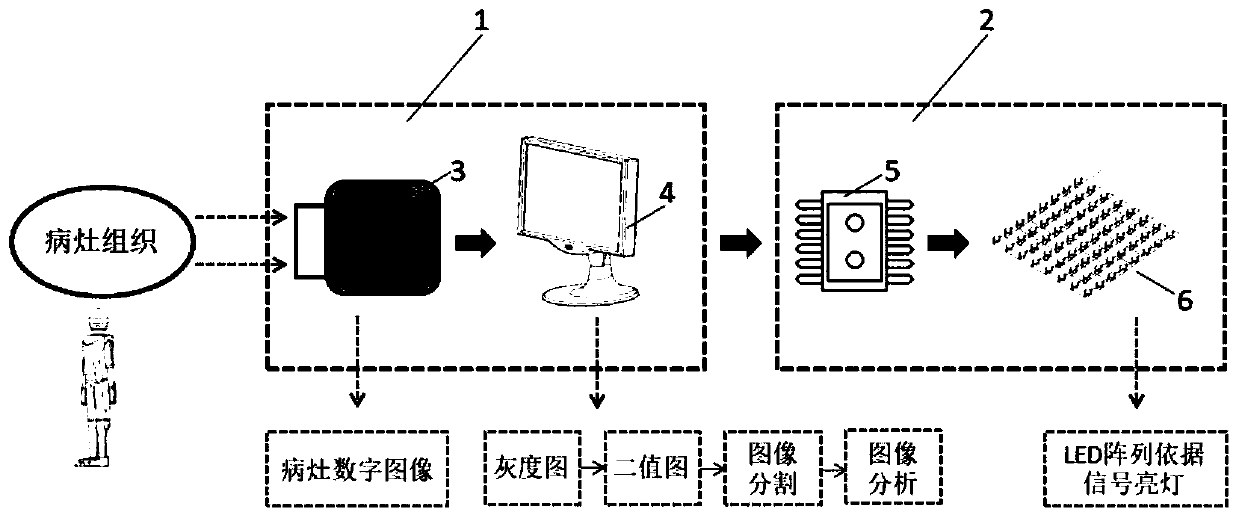
[0022] like figure 1 As shown, the present invention provides an LED array-based intelligent photodynamic therapy lighting system, which mainly includes an image acquisition and processing analysis system 1 and a lighting system 2 . The image acquisition, processing and analysis system includes: a digital image acquisition module 3 and a computer 4 with digital image processing and analysis software. The lighting system includes: a single-chip microcomputer system 5 and an LED array 6 .

[0023] An LED array-based intelligent photodynamic therapy lighting system, the working process of the system is specifically:

[0024] Example 1:

[0025] 1. Image acquisition

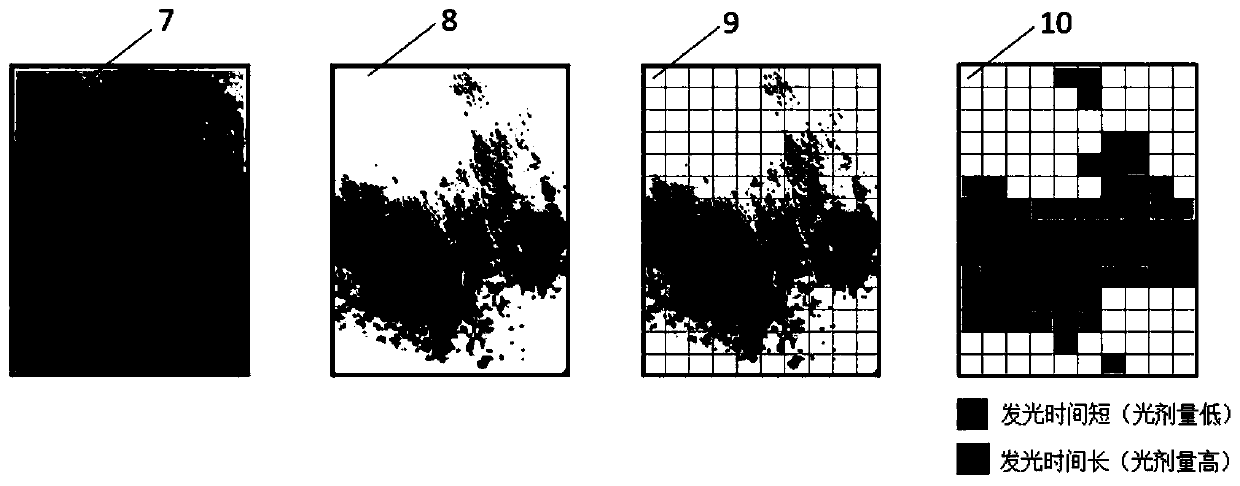
[0026] like figure 1 , through the digital image acquisition module 3, image acquisition is performed on the patient's skin lesion area to obtain a skin lesion image with a scale. Subsequently, the collected images of skin lesions are input into the computer 4 for digital image processing.

[0027] Image Proces...

Embodiment 2

[0038] 1. Image acquisition

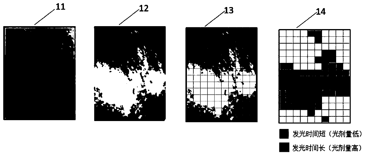
[0039] like figure 1 , through the digital image acquisition module 3, image acquisition is performed on the lesion area of ​​the patient's subcutaneous tumor to obtain an image of the lesion area of ​​the subcutaneous tumor with a scale. Subsequently, the collected lesion image of the subcutaneous tumor is input into the computer 4 for digital image processing.

[0040] 2. Image processing and analysis

[0041] like image 3 , using the computer software MATLAB to perform digital image processing on the collected images of subcutaneous tumor lesions.

[0042] (1) Define the image size. The relationship between the image pixels and the real size is defined according to the scale of the subcutaneous tumor lesion image, so as to define the actual size of the lesion area.

[0043] (2) Obtain the grayscale image 11. Convert the image into a grayscale image with black as the reference color through the grayscale conversion function (rgb2gray).

...


PUM


Abstract

The invention discloses an intelligent photodynamic therapy illumination system based on an LED array. The system comprises a digital image acquisition module, a computer with digital image processingand analyzing software, a single-chip microcomputer system and the LED array. The digital image acquisition tool performs image acquisition on a lesion area to obtain a lesion image with a scale. Thecomputer with the digital image processing and analyzing software is used for carrying out digital image processing on the acquired lesion image to obtain a light-emitting time length signal of eachLED. The single-chip microcomputer system controls the LED array to emit light according to the light-emitting time length signal of each LED. According to the system, the light-emitting area of a light source can be adjusted according to the shape and range of the lesion of a patient; the local illumination dose can be adjusted according to the lesion degree of the area corresponding to the lesion; and therefore the accuracy of the photodynamic therapy process is improved.

Description

technical field [0001] The invention belongs to the application of optics in the medical field, and in particular relates to an LED array-based intelligent photodynamic therapy lighting system. Background technique [0002] Photodynamic therapy is a new treatment method that selectively destroys biological diseased tissues through photochemical reactions to achieve therapeutic purposes. This method has the advantages of minimally invasive, repeatable, and less toxic and side effects, so it has been widely used in the treatment of skin diseases, tumors, dentistry, orthopedics and other diseases, and has also attracted attention in the field of scientific research. The smooth progress of photodynamic therapy requires the cooperation of three major elements: photosensitizer, light source and oxygen molecules. First, the photosensitizer that enters the body through injection or smearing can selectively accumulate in the lesion tissue area, and after a period of time, a photosen...

Claims


Application Information

Patent Timeline
Patent Type & Authority Applications(China)
IPC IPC(8): A61N5/06G06T7/00G06T7/62G16H40/60
CPCA61N5/062A61N2005/0627A61N2005/0652G06T7/0012G06T7/62G16H40/60
Inventor 林立李步洪
Owner FUJIAN NORMAL UNIV
Learn More