
Aluminum or copper laser 3D printing blade face steel bar adhesive tape composite powder scraper

A 3D printing and scraper technology, applied in the improvement of process efficiency, additive manufacturing, additive processing, etc., can solve problems such as residual stress increase, residual stress, scraper hitting parts, etc., to improve connection stability, Avoid bias moment, avoid further deterioration of the effect

Pending Publication Date: 2020-03-24
GUIZHOU POWER GRID CO LTD
View PDF0 Cites 0 Cited by
  • Summary
  • Abstract
  • Description
  • Claims
  • Application Information

AI Technical Summary

Problems solved by technology

[0010] 2. Residual stress
[0015] 3. Crack
[0018] 4. Warping
[0021] 5. Local uplift
Expansion or spheroidization causes local swelling of the aluminum or copper laser 3D printed workpiece, which may cause the risk of the scraper hitting the part
[0023] (2) Causes of defects in aluminum or copper laser 3D printing
[0025] The powder has impurity powder, the powder fluidity is not good, the powder particles are too large, and the powder reflectivity is too large
[0026] 2. Laser parameters are unreasonable
The laser scanning control is unreasonable, and the residual stress will increase
[0028] 3. Unreasonable powder scraping method
However, whether the aluminum or copper laser 3D printing can be successfully completed is closely related to the quality of the aluminum or copper powder scraping powder. At present, the performance of the existing rigid scraping powder and flexible scraping powder is not stable, especially for large cross-sectional area and large thickness. For large-sized and complex workpieces, the probability of successful printing at one time is very low

Method used


Image

  • Aluminum or copper laser 3D printing blade face steel bar adhesive tape composite powder scraper
  • Aluminum or copper laser 3D printing blade face steel bar adhesive tape composite powder scraper
  • Aluminum or copper laser 3D printing blade face steel bar adhesive tape composite powder scraper

Examples


Embodiment 1

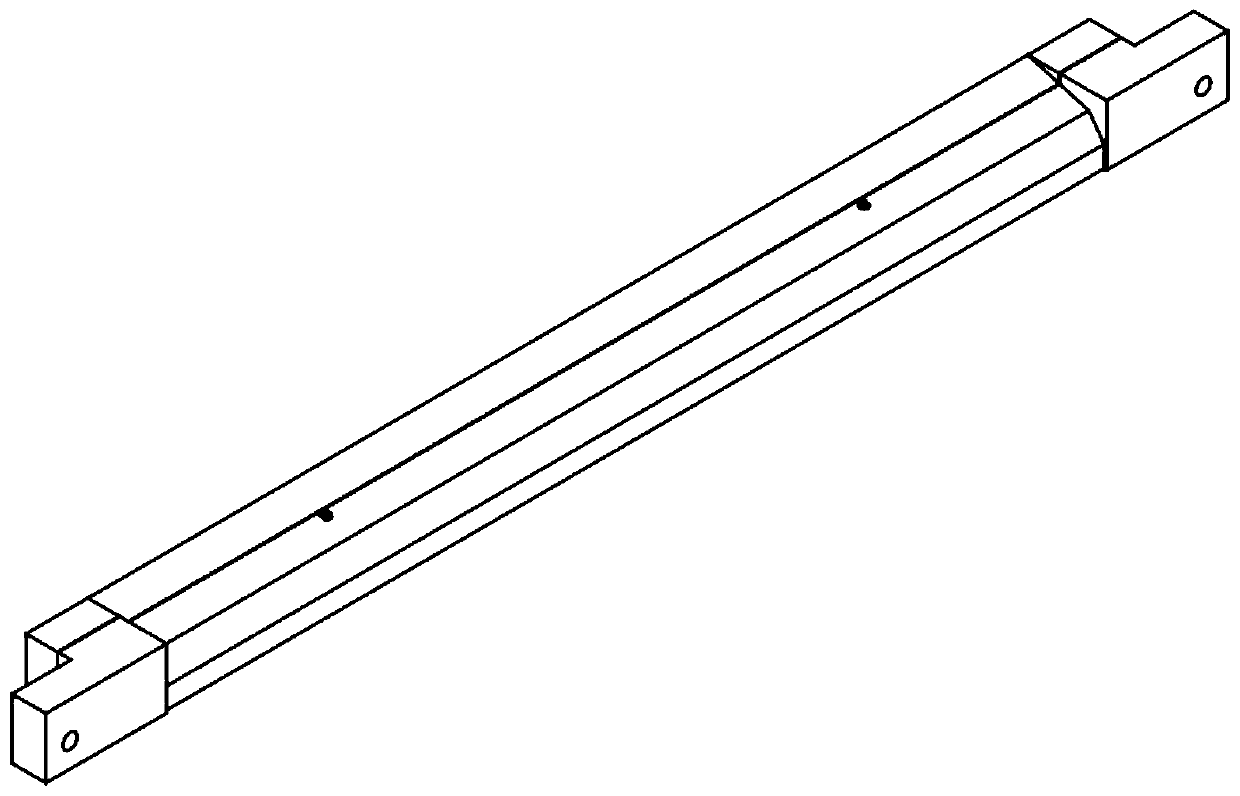
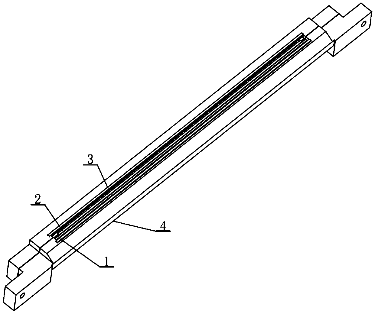
[0060] Embodiment 1: as Figure 1-Figure 8 As shown, an aluminum or copper laser 3D printing edge-surface steel strip rubber compound scraper includes a front K-shaped rubber strip scraper 1, a blade-surface steel strip scraper 2, a rear K-shaped rubber strip scraper 3, and a front K-shaped rubber strip scraper. The strip scraper 1, the steel strip scraper 2 and the rear K-shaped rubber strip scraper 3 are fixedly connected on the knife holder 4, and the steel strip scraper 2 is located in the middle of the front K-shaped rubber strip scraper 1 and the rear K-shaped rubber strip scraper 3.

[0061] Preferably, the blades of the above-mentioned front K-shaped rubber strip scraper 1 and the rear K-shaped rubber strip scraper 3 are in the same plane, and the blade surface steel strip scraper 2 is lower than the front K-shaped rubber strip scraper 1 or the rear K-shaped rubber strip scraper. Blade 0.03-0.05mm of the blade surface of 3.

[0062] Preferably, there is a gap between ...


PUM


Abstract

The invention discloses an aluminum or copper laser 3D printing blade face steel bar adhesive tape composite powder scraper. The scraper comprises a front K-shaped rubber strip scraper, a blade face steel strip scraper and a rear K-shaped rubber strip scraper, the front K-shaped rubber strip scraper, the blade face steel strip scraper and the rear K-shaped rubber strip scraper are fixedly connected to a scraper rest, and the blade face steel strip scraper is located between the front K-shaped rubber strip scraper and the rear K-shaped rubber strip scraper. The K-shaped adhesive tape scraper and the rear K-shaped adhesive tape scraper are symmetrically arranged on the two sides of the blade face steel strip scraper, so the generation of bias torque is avoided, the powder scraping is uniform, and the powder scraping effect of the scraper is improved; the K-shaped adhesive tape scrapers on the two sides are main powder scraping cutters, meanwhile, the blade face steel strip scraper is adopted as an auxiliary cutter, local ultrahigh protrusions and spheroidized molten drops of each layer of printing are planed, and the protrusions are prevented from continuing to deteriorate.

Description

technical field [0001] The invention belongs to the technical field of 3D printing doctor blades, and in particular relates to a compound doctor blade with aluminum or copper laser 3D printing blade surfaces, steel strips and rubber strips. Background technique [0002] Aluminum or copper laser 3D printing is powder bed fusion. Using a laser, the powder particles are fused together point by point, and processed layer by layer until the object is complete. Powder bed fusion systems have heat sources and powder distribution control mechanisms. [0003] During the aluminum or copper laser 3D printing process, a large number of problems that equipment operators try to avoid can occur, including porosity, residual stress, warpage, cracks, localized ridges, etc. [0004] (1) Common defects of aluminum or copper laser 3D printing [0005] 1. Porosity [0006] During the laser 3D printing process of parts, very small holes inside will form porosity, which can be caused by the al...

Claims


Application Information

Patent Timeline
IPC IPC(8): B22F3/105B33Y30/00
CPCB33Y30/00B22F10/00B22F10/28B22F12/67Y02P10/25
Inventor 张仁奇
Owner GUIZHOU POWER GRID CO LTD
Features
  • Generate Ideas
  • Intellectual Property
  • Life Sciences
  • Materials
  • Tech Scout
  • Unparalleled Data Quality
  • Higher Quality Content
  • 60% Fewer Hallucinations
Learn More