Location-welding all-in-one machine for electrical apparatus element pins of assembled circuit board

A technology for assembling circuit boards and electrical components, used in welding equipment, auxiliary devices, metal processing, etc., can solve the problems of slow plugging efficiency, low work efficiency, affecting work efficiency, etc., to facilitate centralized recycling and processing, and improve cutting efficiency. , the effect of simple and convenient operation

Active Publication Date: 2020-03-24
东莞市硕动自动化设备有限公司
View PDF10 Cites 8 Cited by
  • Summary
  • Abstract
  • Description
  • Claims
  • Application Information

AI Technical Summary

Problems solved by technology

[0003] However, in the current market, an all-in-one machine for positioning and welding electrical component pins for assembling circuit boards has the following problems during use. Removing redundant pins of electrical components, this method has low work efficiency, and makes the redundant pins fall directly into the working area after cutting, which cannot guarantee the cleanliness of the working area; b. The electrical component pins of the existing assembled circuit board When the positioning and welding all-in-one machine inserts the pins of electrical components into the metal vias, manual visual alignment is required, and then they are inserted one by one. Affect work efficiency

Method used


Image

  • Location-welding all-in-one machine for electrical apparatus element pins of assembled circuit board
  • Location-welding all-in-one machine for electrical apparatus element pins of assembled circuit board
  • Location-welding all-in-one machine for electrical apparatus element pins of assembled circuit board

Examples


Embodiment Construction

[0026] The embodiments of the present invention will be described in detail below with reference to the accompanying drawings, but the present invention can be implemented in many different ways defined and covered by the claims.

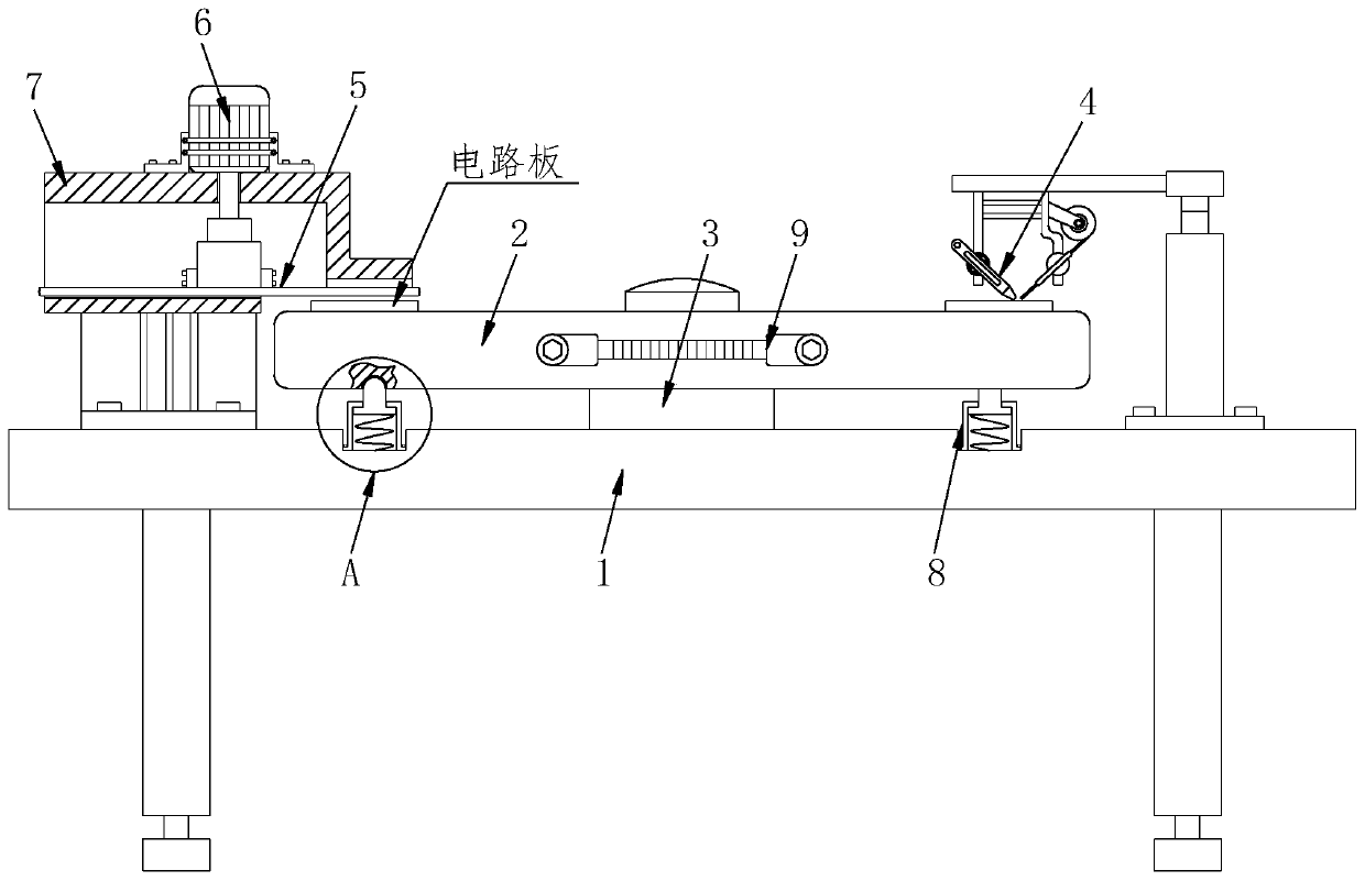
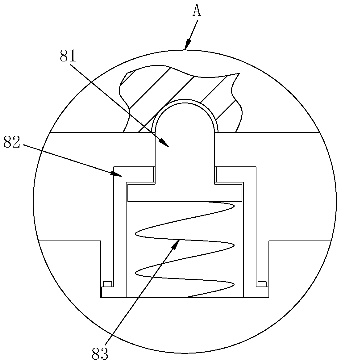
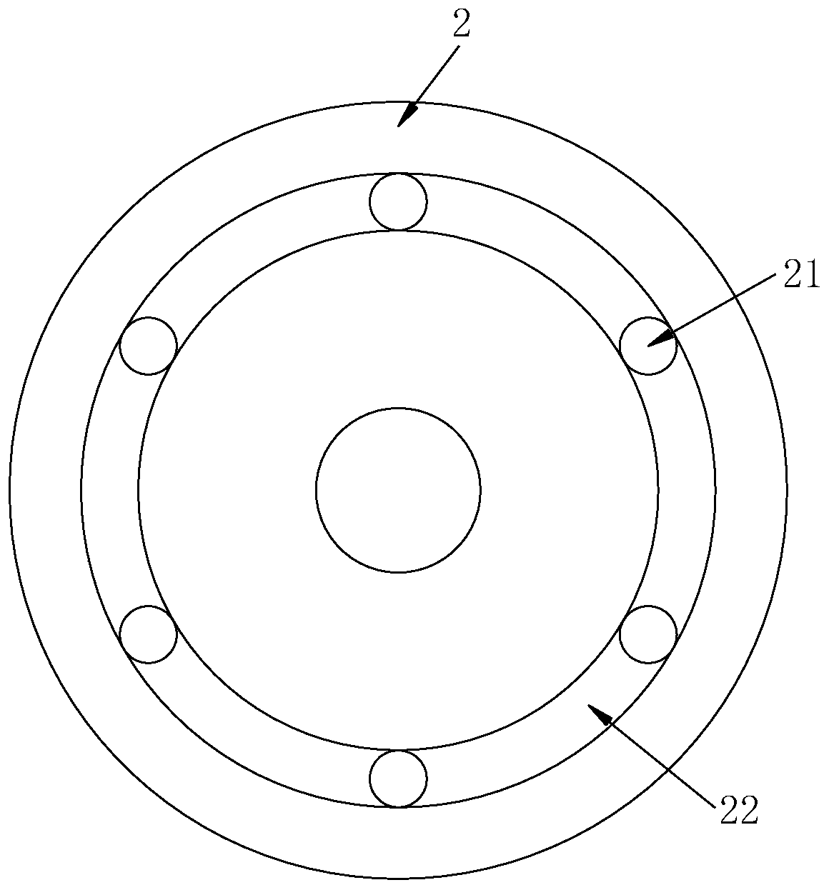
[0027] like Figure 1 to Figure 9 As shown, an all-in-one machine for positioning and welding electrical component pins for assembling circuit boards, including a worktable 1, a placement turntable 2, a rotating shaft 3, a welding torch 4, a cutting assembly 5, a driving motor 6, a fixing frame 7, a positioning assembly 8 and a rotating Handle 9, a rotating shaft 3 is installed at the center of the top of the work surface 1, and the upper end of the rotating shaft 3 is equipped with a placement turntable 2, and the side walls of the placement turntable 2 are equidistantly provided with rotating handles 9, and the top of the work surface 1 is located on the placement turntable The lower end surface area of ​​2 is provided with a positioning assembly ...


PUM


Abstract

The invention relates to a location-welding all-in-one machine for electrical apparatus element pins of an assembled circuit board. The location-welding all-in-one machine for the electrical apparatuselement pins of the assembled circuit board comprises a workbench surface, a placement rotary disc, a rotary shaft, a welding gun, a cutting assembly, a drive motor, a fixed frame, a location assembly and rotary handles, wherein the rotary shaft is installed at the central position of the top of the workbench surface; the placement rotary disc is installed at the upper end of the rotary shaft; the rotary handles are equidistantly arranged on the sidewall of the placement rotary disc; the location assembly is arranged at the top of the workbench surface and in an area on the lower end surfaceof the placement rotary disc; the welding gun is installed at one end of the placement rotary disc; the fixed frame is installed at the other end of the placement rotary disc; the drive motor is installed at the central position of the top of the fixed frame; the cutting assembly is connected to the bottom of the drive motor through a shaft coupling; and a circular rail is formed at the bottom ofthe placement rotary disc. According to the location-welding all-in-one machine for the electrical apparatus element pins of the assembled circuit board, the electrical apparatus element pins can be rapidly inserted into metal through holes; and moreover, the location-welding all-in-one machine for the electrical apparatus element pins of the assembled circuit board is appliable to different typesof circuit boards, and capable of rapidly and effectively cutting redundant pins.

Description

technical field [0001] The invention relates to the technical field of circuit board processing machinery, in particular to an all-in-one machine for positioning and welding electrical component pins for assembling circuit boards. Background technique [0002] The circuit board, also known as the printed circuit board, is an important electronic component, a support for electronic components, and a carrier for the electrical connection of electronic components. The circuit board makes the circuit miniaturized and intuitive, and is used for mass production and optimization of fixed circuits. Electrical layout plays an important role. Circuit boards may be referred to as printed wiring boards or printed circuit boards. Electronic components are basic elements in electronic circuits, usually individually packaged, and have two or more leads or metal contacts. Electronic components must be connected to each other to form an electronic circuit with specific functions, such as a...

Claims


Application Information

Patent Timeline
Patent Type & Authority Applications(China)
IPC IPC(8): B23K3/00B23K3/08
CPCB23K3/00B23K3/08
Inventor 王强顾小东
Owner 东莞市硕动自动化设备有限公司
Why Eureka
Try Eureka