A low-cost modular composite molding tooling manufacturing method

A composite material and forming tooling technology, applied in the field of tooling manufacturing, can solve the problems of unsuitable small batch composite material product forming tooling, high material cost and manufacturing cost, large thermal expansion coefficient, etc., and achieve easy correction and maintenance, follow-up maintenance. The effect of convenience and shortening the manufacturing cycle

Active Publication Date: 2021-07-27
SHENYANG AEROSPACE UNIVERSITY
View PDF0 Cites 0 Cited by
  • Summary
  • Abstract
  • Description
  • Claims
  • Application Information

AI Technical Summary

Problems solved by technology

With the requirements of the application field for the surface accuracy and dimensional accuracy of composite products and the continuous improvement of the manufacturing efficiency of composite products, traditional metal molds have been used as mold materials due to the existence of problems such as large thermal expansion coefficient, heavy weight, and slow response. Gradually unable to meet the development of the composite material industry; compared with this, composite material tooling is more and more used in composite materials due to its advantages such as good thermal expansion performance matching, low density, small heat capacity, and certain repairability. product manufacturing process
[0003] However, traditional composite material tooling is generally manufactured with tooling prepreg. Although multiple sets of composite material tooling can be remanufactured from one master mold, which is conducive to satisfying the mass manufacturing process of composite material products, it will result in high material costs. and manufacturing costs, it is not suitable for manufacturing molding tools in the development stage of small batches of composite material products with high dimensional accuracy requirements

Method used


Image

  • A low-cost modular composite molding tooling manufacturing method

Examples


Embodiment Construction

[0027] The content disclosed in the present invention includes the combined form of the composite material forming tooling, the backing of the tooling profile, the mating surface of the tooling profile, the selection of materials, connection methods, and molding methods involved in the process of manufacturing, replacing and correcting the tooling profile and other key technical points should be regarded as the scope of protection of the present invention.

[0028] The present invention will be further described below in conjunction with specific examples of implementation, but the present invention is not limited to these examples.

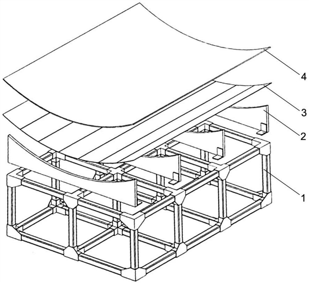
[0029] A method for manufacturing low-cost modular composite material forming tooling, comprising the following steps:

[0030] Step 1: Use riveting to connect the composite material square tube (DS1207.3) through a tee to form a tooling frame 1, and reserve an assembly hole on the side of the tooling frame 1 close to the tooling surface;

[003...


PUM

PropertyMeasurementUnit
bending strengthaaaaaaaaaa
compressive strengthaaaaaaaaaa
modulusaaaaaaaaaa

Abstract

A low-cost modular composite material forming tooling manufacturing method belongs to the technical field of tooling manufacturing. (4) making the tooling profile, (5) pasting the tooling profile; the method of the present invention can omit the manufacturing process of the master mold, and use a small amount of tooling frame structure to match a variety of tooling profiles with different profile profiles, The manufacturing, replacement and correction of composite tooling are completed through material layup and accumulation, curing and processing. It is suitable for the manufacturing process of forming tooling in the research and development stage of small-batch composite products with high profile and dimensional accuracy requirements. Save R&D costs and shorten the R&D cycle.

Description

technical field [0001] The invention belongs to the technical field of tooling manufacturing, and in particular relates to a low-cost modular composite material forming tooling manufacturing method. Background technique [0002] Composite products often use aluminum, high-strength steel, Invar, and carbon fiber composite materials as the preferred materials for forming tooling, and considering thermal efficiency, temperature uniformity, and operability, most of them are based on frame structures. With the requirements of the application field for the surface accuracy and dimensional accuracy of composite material products and the continuous improvement of the manufacturing efficiency of composite material products, traditional metal molds have been used as mold materials due to the existence of problems such as large thermal expansion coefficient, heavy weight, and slow response. Gradually unable to meet the development of the composite material industry; compared with this,...

Claims


Application Information

Patent Timeline
Patent Type & Authority Patents(China)
IPC IPC(8): B29C70/44B29C70/54B29C33/38
CPCB29C33/3842B29C70/44B29C70/54
Inventor 贾彩霞王乾李志歆许朋梁禄忠关振
Owner SHENYANG AEROSPACE UNIVERSITY
Why Eureka
Try Eureka