Dynamic-sounding automatic test instrument and implementation method
A technology of automatic testing and dynamic penetration testing, which is applied in the field of foundation soil surveying, construction, infrastructure engineering, etc., can solve the problems of insufficient efficiency, cumbersome process, and labor-intensive energy, so as to improve the speed and accuracy, and improve the detection accuracy , Improve the effect of measurement accuracy
- Summary
- Abstract
- Description
- Claims
- Application Information
AI Technical Summary
Problems solved by technology
Method used
Image
Examples
Embodiment 1
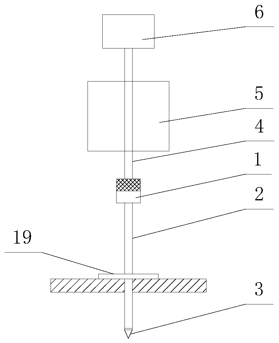
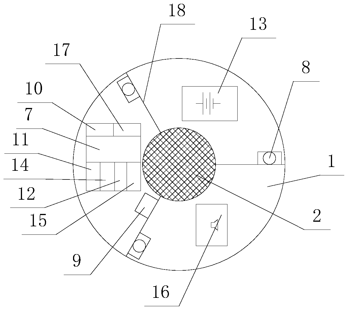
[0031] Such as Figure 1 ~ Figure 5 As shown, this embodiment provides an automatic test instrument for dynamic penetration, including hammer base 1, drill rod 2, probe 3, guide rod 4, penetrating hammer 5, automatic decoupling device 6, data processing module 7, laser ranging module 8. Acceleration module 9, power supply module 13, storage module 14, status indication module 15, and sound alarm module 16.
[0032] The upper part of the hammer base 1 is a solid cylinder made of steel, and its bottom center is connected with a vertical drill pipe 2 through threads. The lower end of the drill pipe 2 is equipped with a probe 3, and the drill pipe 2 and the probe 3 are of internationally prescribed materials And the standard equipment of the model, the bottom of the hammer seat 1 is equipped with an equipment compartment, and the drill rod 2 penetrates the equipment compartment. The top of the hammer seat 1 is vertically installed with a guide rod 4, a piercing hammer 5 is movably i...
Embodiment 2
[0045] Such as Image 6 As shown, this embodiment is basically the same as Embodiment 1. Only the laser ranging module 8 is provided with three, and there are three central partitions 18 for installing the laser ranging module 8 in the equipment compartment. The plate 18 is uniformly distributed in a ring shape with the vertical axis of the drill pipe 2 as the center; the three laser ranging modules 8 are respectively installed on different middle partitions 18, and the three laser ranging modules 8 are connected to the axis of the drill pipe 2 The distances r are equal, and the acceleration module 9 is installed on any central partition 18. The outer wall of the equipment warehouse is provided with three knobs for adjusting the initial value of the inclination of the laser ranging module 8. By manually rotating the knobs, the verticality of the laser beam emitted by the laser ranging module 8 can be adjusted.
[0046] During specific detection in this embodiment, the following s...
Embodiment 3
[0056] This embodiment is basically the same as Embodiment 1, except that a positioning module 11 connected to the data processing module 7 is added to the equipment warehouse. The positioning module 11 is used to measure the position coordinates of the borehole, and by measuring the coordinate data of the borehole position twice before and after, it can determine whether the borehole position has shifted. First, the coordinate data of the detection position (X 1 , Y 1 ,Z 1 ), when starting to probe the borehole, the coordinate data (X 2 , Y 2 ,Z 2 ), the data is sent to the data processing module 7 and compared with the positioning accuracy value A of the positioning module 11. If the lateral displacement is within the set interval, the drilling position is considered normal, and the subsequent steps are continued. If it is not satisfied, it is determined The drilling has shifted or deviated from the design value. At this time, the data processing module 7 controls the operatio...
PUM
 Abstract
Description
Claims
Application Information
 - R&D
- Intellectual Property
- Life Sciences
- Materials
- Tech Scout
- Unparalleled Data Quality
- Higher Quality Content
- 60% Fewer Hallucinations
Browse by: Latest US Patents, China's latest patents, Technical Efficacy Thesaurus, Application Domain, Technology Topic, Popular Technical Reports.
© 2025 PatSnap. All rights reserved.Legal|Privacy policy|Modern Slavery Act Transparency Statement|Sitemap|About US| Contact US: help@patsnap.com


