Stepping motor subdivision control system and control method thereof

A technology of stepper motor and control method, which is applied in the direction of control system, motor generator control, electrical components, etc., and can solve the problem of large errors in winding current approximation to sine and cosine curves, increased triode switching loss and failure risk, and motor rotation Reduced stability and other issues to achieve the effect of reducing failure links, overcoming high-precision positioning problems, and reducing implementation costs

Active Publication Date: 2020-03-24
SHANGHAI RADIO EQUIP RES INST
View PDF6 Cites 4 Cited by
  • Summary
  • Abstract
  • Description
  • Claims
  • Application Information

AI Technical Summary

Problems solved by technology

The disadvantages of this solution are: (1) There are many burrs in the winding current during the motor rotation process. Compared with the sine and cosine signals, the PWM signal frequently jumps, which makes the power amplifier circuit switch frequently, which increases the switching loss and failure risk of the triode tube. , and the error of the winding current approaching the sine-cosine curve is also large, and the stability of the motor rotation is reduced; (2) The existence of the D / A conversion circuit not only increases the cost, but also adds a failure link, especially in satellites. In high-reliability scenarios, reducing a series link can better ensure system reliability
[0009] In the 6th issue of 2016 "Development and Innovation of Electromechanical Products", the published document "Simulink Simulation of Stepper Motor Subdivision Drive Technology" analyzed the principle of stepper motor subdivision drive technology in detail, and built a subdivision based on Matlab / Simulink Control model, which needs to convert the winding current into a digital signal through the A / D converter and perform closed-loop control of the current in the controller. The project implementation of this scheme is relatively complicated

Method used


Image

  • Stepping motor subdivision control system and control method thereof
  • Stepping motor subdivision control system and control method thereof
  • Stepping motor subdivision control system and control method thereof

Examples


Embodiment Construction

[0042]The technical solutions of the present invention will be clearly and completely described below in conjunction with the accompanying drawings. Apparently, the described embodiments are some of the embodiments of the present invention, but not all of them. Based on the embodiments of the present invention, all other embodiments obtained by persons of ordinary skill in the art without making creative efforts belong to the protection scope of the present invention.

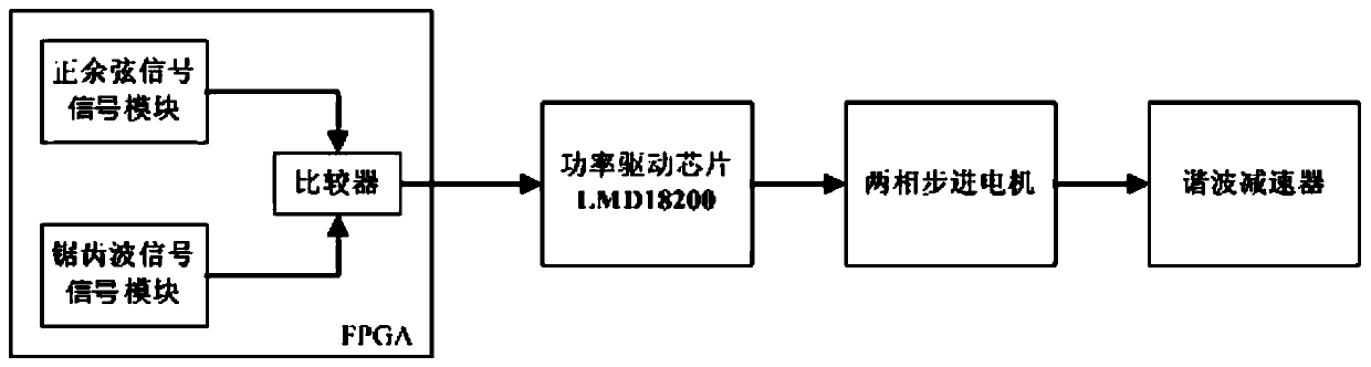
[0043] On the one hand, the present invention provides a stepper motor subdivision control system, such as figure 1 As shown, the system includes:

[0044] FPGA, power driver chip, stepper motor and harmonic reducer connected in sequence;

[0045] Among them, the FPGA contains,

[0046] Sin-cosine signal module, output sine-cosine signal;

[0047] The sawtooth wave signal module outputs a sawtooth wave signal;

[0048] Comparator module, the sine-cosine signal output by the sine-cosine signal module and the...


PUM


Abstract

The invention discloses a stepping motor subdivision control system and a control method thereof. The system comprises an FPGA, a power driving chip, a two-phase stepping motor and a harmonic reducerwhich are connected in sequence. The FPGA comprises a comparator module, a sine and cosine signal module, outputting sine and cosine signals to the comparator module; a sawtooth wave signal module, outputting sawtooth wave signals to the comparator module. The comparator module compares the sine and cosine signals with the sawtooth wave signals and outputs PWM signals, and the duty ratio of the PWM signals changes according to the rule of the sine and cosine signals. According to the stepping motor subdivision control method provided by the invention, a D / A conversion circuit in a traditionalstepping motor control scheme is deleted, and a PWM signal is generated directly through a digital signal comparison mode to drive the stepping motor to rotate, so that the engineering cost is reduced, and the system reliability is improved.

Description

technical field [0001] The invention relates to the technical field of stepping motors, in particular to a stepping motor subdivision control system and a control method thereof. Background technique [0002] A stepper motor is an open-loop control element that converts electrical pulse signals into angular displacement or linear displacement. In the case of non-overload, the speed and stop position of the motor only depend on the frequency and number of pulses of the pulse signal, and are not affected by the load change. When the stepper driver receives a pulse signal, it will drive the stepper motor to press The set direction turns a fixed angle, which is called "step angle", and its rotation runs step by step at a fixed angle. The angular displacement can be controlled by controlling the number of pulses, so as to achieve the purpose of accurate positioning; at the same time, the speed and acceleration of the motor rotation can be controlled by controlling the pulse freq...

Claims


Application Information

Patent Timeline
Patent Type & Authority Applications(China)
IPC IPC(8): H02P8/18
CPCH02P8/18
Inventor 赵建华周起华王文晴魏颖李鸿志
Owner SHANGHAI RADIO EQUIP RES INST
Why Eureka
Try Eureka