Electric industrial vehicle integrated power system and control method thereof

A technology for electric industrial vehicles and power systems, applied in the direction of electric power devices, control devices, power devices, etc., can solve the problem of reducing the temperature rise of electric industrial vehicle drive and hydraulic power subsystems, heat dissipation efficiency and functions are not easy to achieve, and affect the use of electric energy Efficiency and other issues, to achieve the effect of reducing assembly and installation procedures, facilitating vehicle installation, and simple structure

Pending Publication Date: 2020-03-27
ANHUI WEIDE POWER SUPPLY CO LTD
View PDF0 Cites 5 Cited by
  • Summary
  • Abstract
  • Description
  • Claims
  • Application Information

AI Technical Summary

Problems solved by technology

[0004] The purpose of the present invention is to propose an integrated power system of electric industrial vehicles and its control method, which is used to solve the problem that the existing electric forklift drive and hydraulic power system have a single technical route, and the length of connecting cables in the system is too long, which is not conducive to the assembly of the whole vehicle. , and if the cable is too long, it will increase the cost and affect the efficiency of power use, and the heat dissipation efficiency and function are not easy to realize, and each unit needs to be cooled or dissipated separately, resulting in a very complicated structure and a large increase in cost; the invention is highly integrated , The layout is compact, the structure is completely integrated into a unified whole, no need for distributed layout, the structure is simple, easy to install on the whole vehicle, and the integration

Method used


Image

  • Electric industrial vehicle integrated power system and control method thereof
  • Electric industrial vehicle integrated power system and control method thereof
  • Electric industrial vehicle integrated power system and control method thereof

Examples


Embodiment Construction

[0037] The technical solutions of the present invention will be clearly and completely described below in conjunction with the embodiments. Apparently, the described embodiments are only some of the embodiments of the present invention, not all of them. Based on the embodiments of the present invention, all other embodiments obtained by persons of ordinary skill in the art without creative efforts fall within the protection scope of the present invention.

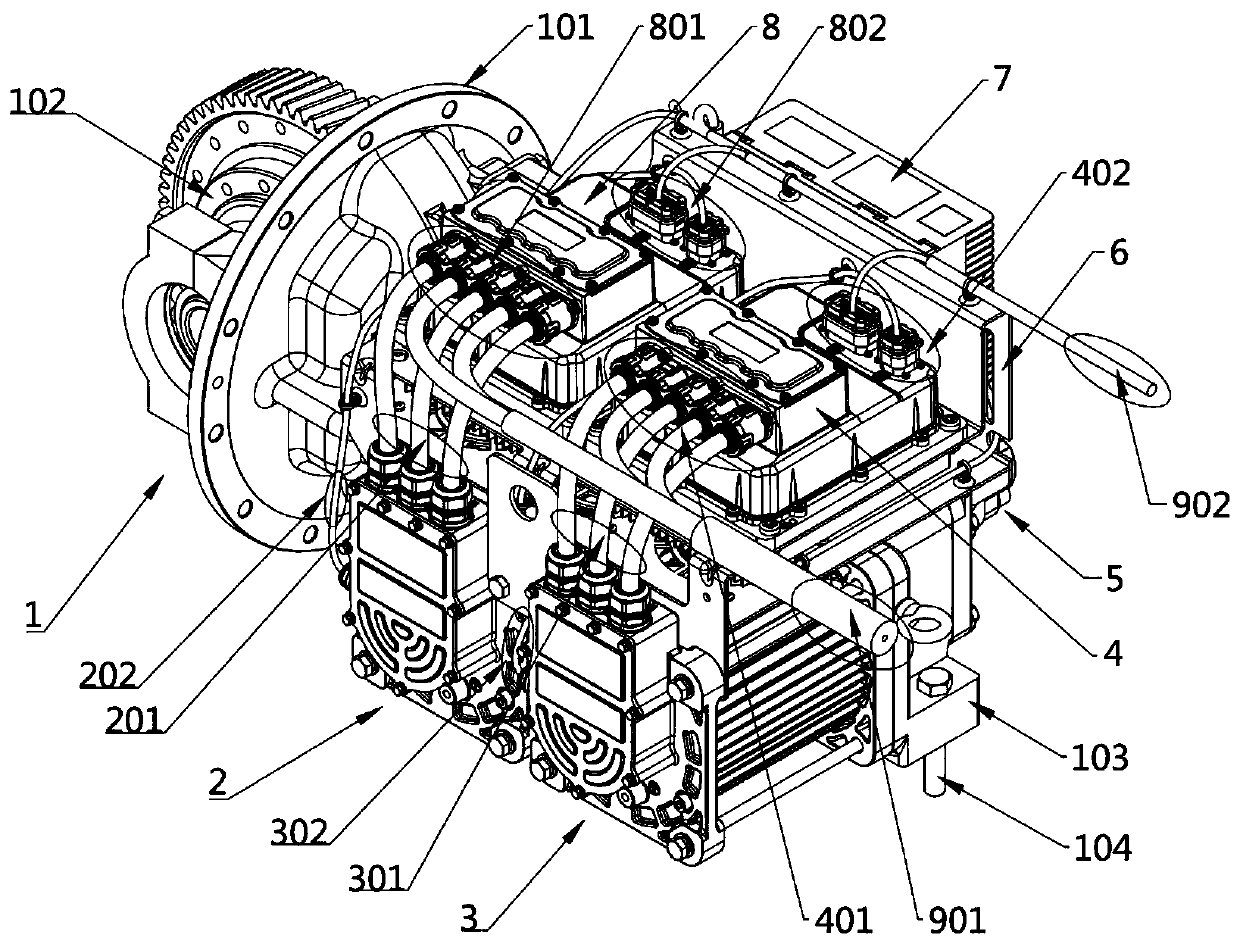
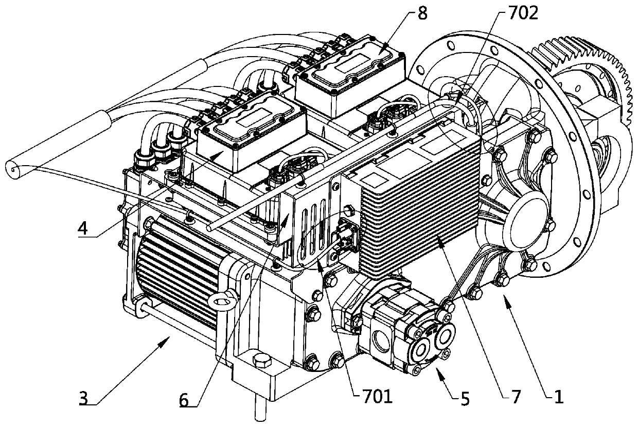
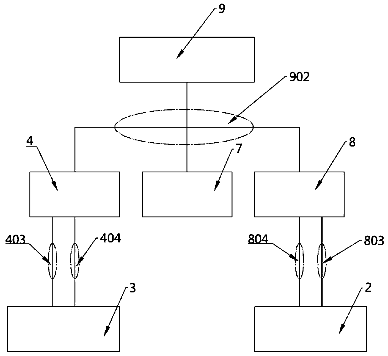
[0038] see Figure 1-9 As shown, an integrated power system of an electric industrial vehicle includes a drive power subsystem, a hydraulic power subsystem and an upper power control subsystem;

[0039] The drive power subsystem comprises a drive motor 2, a drive motor controller 8 and a drive motor transmission mechanism 105; the output shaft of the drive motor 2 is coaxially connected with the input shaft 17 of the drive motor transmission mechanism 105 by a spline 15, and fixed Installed on the housing of the integrated...


PUM


Abstract

The invention discloses an electric industrial vehicle integrated power system and a control method thereof. The technical problem that an existing electric forklift driving and hydraulic power systemis single in technical route is solved. The problems that a connecting cable in a system is too long, assembly of a whole vehicle is not facilitated, the cost is increased and the use efficiency of electric energy is affected due to the fact that the cable is too long, the heat dissipation efficiency and functions are not easy to achieve, each unit needs to be cooled or dissipated independently,the structure is very complex, and the cost is greatly increased are solved. The system comprises a driving power subsystem, a hydraulic power subsystem and an upper power control subsystem, the device is highly integrated, compact in arrangement, simple in structure and convenient to install the whole vehicle, and the structure is completely integrated into a unified whole; the high-voltage wireharness and the low-voltage wire harness are directly connected in a short distance, so that the connection length of external cables among all parts of the integrated power system is greatly reduced,and the length of the cables is reduced; and a cooling fan is arranged.

Description

technical field [0001] The invention belongs to the field of electric industrial vehicles and relates to an integrated power system technology of electric industrial vehicles, in particular to an integrated power system of electric industrial vehicles and a control method thereof. Background technique [0002] China's industrial vehicle market has a broad space for development, especially the market potential of electric industrial vehicles is huge. With the continuous development of the economy, higher requirements are put forward for the electric industrial vehicle drive and hydraulic power system. [0003] The existing electric industrial vehicle drive and hydraulic power system have a single technical route, basically using the drive motor and the front axle reducer to form the walking power unit, the oil pump motor and the oil pump to form the hydraulic power unit, and the drive motor controller and the oil pump motor controller to be arranged separately. Motor control...

Claims


Application Information

Patent Timeline
IPC IPC(8): B60K1/00B60K17/12B60R16/02H05K7/20B66F9/22B66F9/24
CPCB60K1/00B60K17/12B60R16/02H05K7/20B66F9/22B66F9/24
Inventor 项寿南陈建
Owner ANHUI WEIDE POWER SUPPLY CO LTD
Why Eureka
Try Eureka