Hydraulic device for cooling at least two wet-running clutches in motor vehicle

A wet clutch and hydraulic device technology, applied in the field of hydraulic devices, can solve undesired problems and achieve the effect of avoiding excessive supply

Pending Publication Date: 2020-03-31
FTE汽车有限责任公司
View PDF14 Cites 0 Cited by
  • Summary
  • Abstract
  • Description
  • Claims
  • Application Information

AI Technical Summary

Problems solved by technology

Similar to the solenoid valves described above, in particular a switching unit provided with a stop and a sen

Method used


Image

  • Hydraulic device for cooling at least two wet-running clutches in motor vehicle

Examples


Embodiment Construction

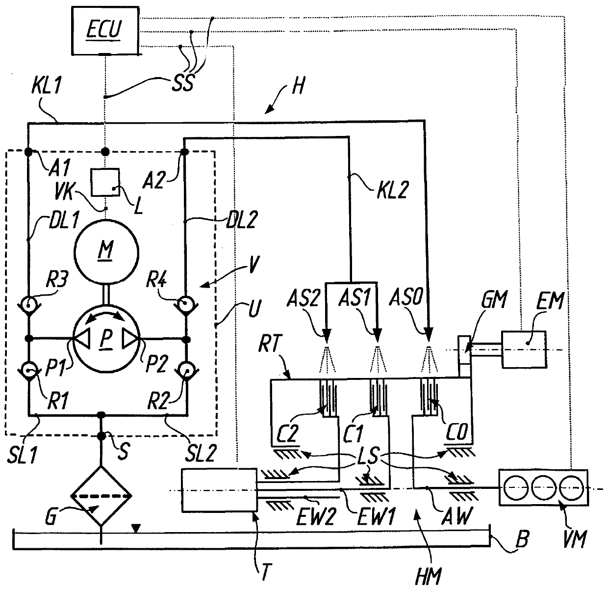
[0021] exist figure 1 , reference numeral H generally identifies a hydraulic device for cooling at least two (in the exemplary embodiment shown, three) wet clutches C0 , C1 , C2 in a motor vehicle. In this case, the three clutches C0, C1, C2 are hybrid transmission module HM (only in figure 1 shown schematically in ), which in particular comprises a dual clutch arrangement with first and second (partial) clutches C1, C2 for shifting of an automatically shifted transmission T (dual clutch transmission) and for coupling or Specifically the (disconnecting) clutch C0 of the internal combustion engine VM is disengaged. In this case, a corresponding actuation system (not shown) is associated with each clutch C0, C1, C2 for independent actuation.

[0022] The rotating part RT of the hybrid transmission module HM is permanently drivingly connected to the electric motor EM via the transmission mechanism GM, the rotating part RT can be alternately drivingly connected to the output sha...


PUM


Abstract

A hydraulic device for cooling at least two wet-running clutches comprises a reversing pump for conveying a coolant liquid, wherein one pump connection is on the suction side and the other pump connection is on the pressure side depending on the direction of rotation of the pump, and comprising a suction inlet for sucking coolant liquid from the reservoir container, a first outlet for conveying coolant liquid to the first clutch and a second outlet for conveying coolant liquid to at least one second clutch. The aim of the invention is to guide a coolant liquid from a suction opening to each outlet associated with one of the pump connections on the pressure side. According to the invention, a valve arrangement having four non-return valves is provided, which are arranged between the pump connection, the suction opening and the outlet such that coolant liquid can only be suctioned through the suction opening on the suction side and can only be conveyed in the direction of the associatedoutlet on the pressure side. By switching the direction of rotation of the pump, the drawn coolant liquid can thus be conducted to the first outlet or the second outlet by means of the valve arrangement.

Description

technical field [0001] The invention relates to a hydraulic device for cooling at least two wet-running clutches in a motor vehicle according to the preamble of claim 1 . In particular, the invention relates to such a device, which at the same time is already widely used in the automotive industry for hybrid vehicles with or without dual clutch transmissions. Background technique [0002] The use of wet clutches in dual-clutch transmissions (DCT, double-clutch transmissions) and hybrid transmission modules with multiple clutch units (DHT = dedicated hybrid transmission, D dedicated H ybrid T transmissions) because wet clutches are advantageous in terms of lower moment of inertia, higher torque capacity and smaller installation space requirements compared to forced oil cooling of dry clutches. At the same time, one disadvantage of wet clutches relative to dry clutches is the greater drag torque of wet clutches. This can be improved by cooling on demand, for which a soleno...

Claims


Application Information

Patent Timeline
IPC IPC(8): F16H57/04F16D13/72F16D25/12
CPCF16H57/0412F16H57/0473F16D13/72F16D25/123F16D2300/0214F16D13/52F16H57/0441F16H57/0435F16D48/062F16D13/74F16D21/06F16D25/14
Inventor W.霍伊布纳
Owner FTE汽车有限责任公司
Why Eureka
Try Eureka