Method and device for detecting laser spot scanning accuracy of laser processing equipment

A laser processing and laser spot technology, which is used in measuring devices, optical instrument testing, and machine/structural component testing. Solve problems such as the difficulty of the problem, and achieve the effect of enriching the detection methods of laser precision processing, intuitive and accurate measurement methods, and simplifying the proofing detection process

Active Publication Date: 2021-05-04
湖南省鹰眼在线电子科技有限公司
View PDF8 Cites 0 Cited by
  • Summary
  • Abstract
  • Description
  • Claims
  • Application Information

AI Technical Summary

Problems solved by technology

In the manufacturing of processing equipment and industrial production applications, the proofing test is usually used for inspection, and the optical imaging microscope is used to check whether the processing pattern conforms to the input drawing. This method has the following disadvantages: On the one hand, for complex patterns, it is difficult to obtain full The processing trajectory of the format matches the accuracy data; on the other hand, the target material of the proofing test is not reusable, and cannot fundamentally reproduce the processing and scanning process of the spot, which increases the difficulty of analyzing and solving problems; It may be repeated many times, which will inevitably lead to waste of materials, which is not conducive to cost control in the case of mass industrial production

Method used


Image

  • Method and device for detecting laser spot scanning accuracy of laser processing equipment
  • Method and device for detecting laser spot scanning accuracy of laser processing equipment
  • Method and device for detecting laser spot scanning accuracy of laser processing equipment

Examples


Embodiment Construction

[0057] The preferred embodiments of the present invention will be described in further detail below in conjunction with the accompanying drawings.

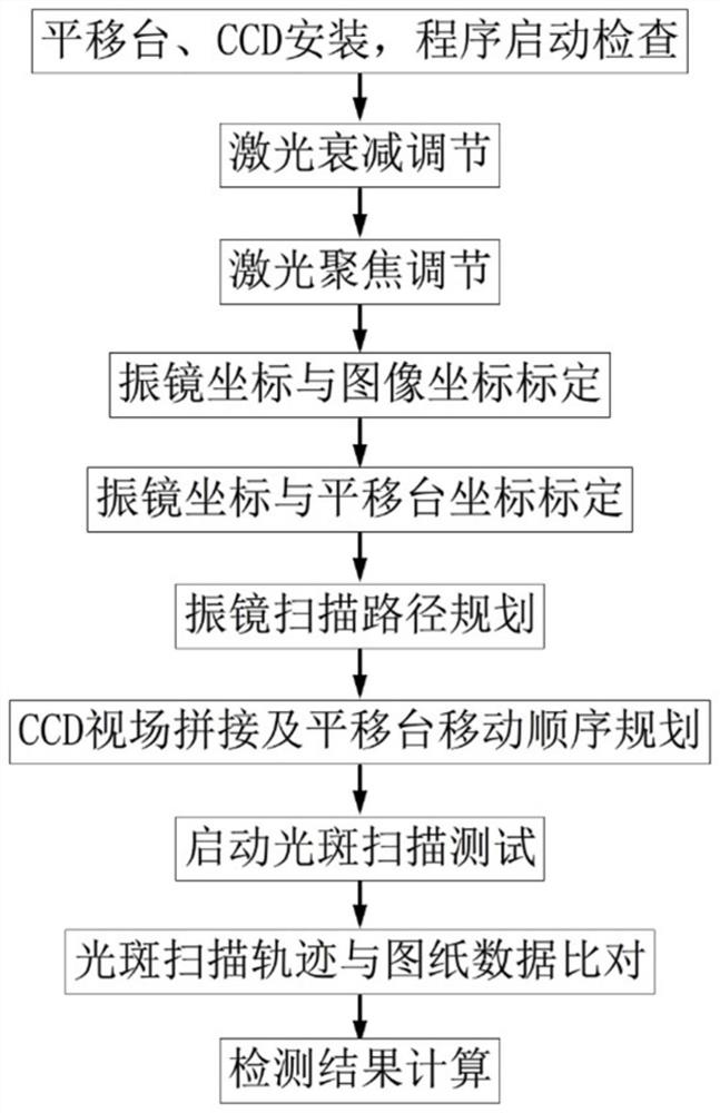
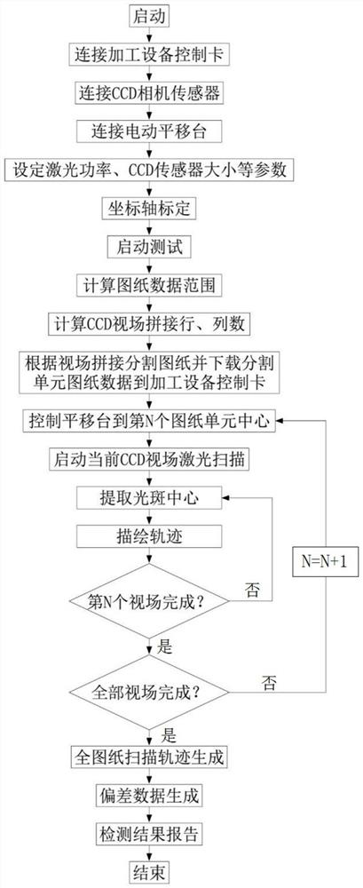
[0058] Such as figure 1 and figure 2 As shown, the preferred embodiment of the laser spot scanning accuracy detection method of the laser processing equipment includes the following steps:

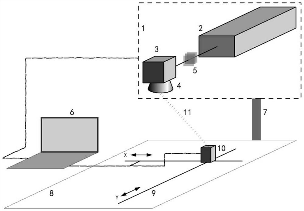
[0059] In step 1, the translation stage 9 and the CCD camera 10 are installed, and the program is started for inspection.

[0060] A high-precision two-dimensional electric translation platform 9 is set on the working surface 8 of the laser processing equipment. The translation platform 9 can move along the horizontal and vertical directions of the working surface 8, and the center of the moving range of the translation platform 9 is aligned with the center of the processing area. ; Install a lens-removing CCD camera 10 on the translation stage 9; wherein, the photosensitive surface of the CCD camera 10 is aimed at the laser beam 11 output ...


PUM


Abstract

The invention discloses a laser spot scanning accuracy detection method and device for laser processing equipment, wherein the detection method includes: setting a translation platform on the working surface; installing a CCD camera on the translation platform; laser attenuation magnification and focus adjustment; calibration of the vibrating mirror coordinates coordinates with the CCD camera; calibrate the coordinates of the galvanometer and the translation stage; plan the laser scanning path and the movement sequence of the translation stage according to the processing drawing data and the field of view of the CCD camera; perform laser scanning and output the images collected by the CCD camera; obtain the current view The actual spot scanning trajectory under the field; after the laser scans the drawing corresponding to the current field of view, move the camera to the next position according to the specified path; repeat the scanning analysis until the entire drawing is scanned by the laser; compare the scanning track of the spot And the drawing data to get the scanning accuracy. The invention directly detects the laser scanning accuracy of the drawings to be processed before the drawings are processed, which can improve product quality and production efficiency, and reduce production costs.

Description

technical field [0001] The invention belongs to the technical field of laser precision machining, and in particular relates to a laser spot scanning precision detection method and device of laser processing equipment. Background technique [0002] Laser processing technologies such as laser marking, cutting, and surface treatment are booming due to their advantages of non-contact, no tool loss, and wide range of materials. With the advancement of technology and the deepening of industrial applications, the workpieces to be processed are becoming more and more precise, and the processing drawings are becoming more and more complex, which puts forward higher requirements for laser precision processing. The quality of the laser beam is required to be better, so as to obtain a smaller focused spot with a cross-sectional spot distribution that meets the requirements; the control system is required to be more precise, so that the track of the spot on the target surface is more in ...

Claims


Application Information

Patent Timeline
Patent Type & Authority Patents(China)
IPC IPC(8): G01M11/00G01M11/02
CPCG01M11/00G01M11/0257
Inventor 朱志武姜广文伏思华雷志辉
Owner 湖南省鹰眼在线电子科技有限公司
Why Eureka
Try Eureka