
Impurity separator for rare earth permanent magnetic materials for civil engineering

A technology of rare earth permanent magnet and civil engineering, which is applied in the direction of solid separation, filter screen, grid, etc., can solve the problems of poor corrosion resistance, waste of rare earth resources, loss of magnetic properties, etc., achieve simple and convenient operation, improve crushing effect, and accelerate The effect of feeding speed

Inactive Publication Date: 2020-04-03
ZHENGZHOU INST OF TECH
View PDF8 Cites 9 Cited by
  • Summary
  • Abstract
  • Description
  • Claims
  • Application Information

AI Technical Summary

Problems solved by technology

[0009] Although the rare earth permanent magnet material has the most superior magnetic properties, it also has serious weaknesses, one of which is poor corrosion resistance. The electrochemical corrosion potential of the Nd-rich phase of the rare earth permanent magnet is extremely low, and it is easy to oxidize, absorb hydrogen and hydrolyze. , so rare earth permanent magnets can degrade rapidly in a certain environment and lose their magnetic properties
If these corroded and degraded rare earth permanent magnet materials are discarded directly, it will cause a waste of rare earth resources. Therefore, there are successive methods of using waste rare earth permanent magnet materials to regenerate high-performance permanent magnets.
[0010] However, in the process of recycling waste rare earth permanent magnet materials, impurity removal is a very important part. If manual picking is used, since the waste rare earth permanent magnet materials still have a certain degree of magnetism, it is difficult to remove impurities. Recycling The efficiency is not high, so it is necessary to design a kind of impurity separator for rare earth permanent magnet materials used in civil engineering to improve the efficiency of impurity removal

Method used


Image

  • Impurity separator for rare earth permanent magnetic materials for civil engineering
  • Impurity separator for rare earth permanent magnetic materials for civil engineering
  • Impurity separator for rare earth permanent magnetic materials for civil engineering

Examples


Embodiment 1

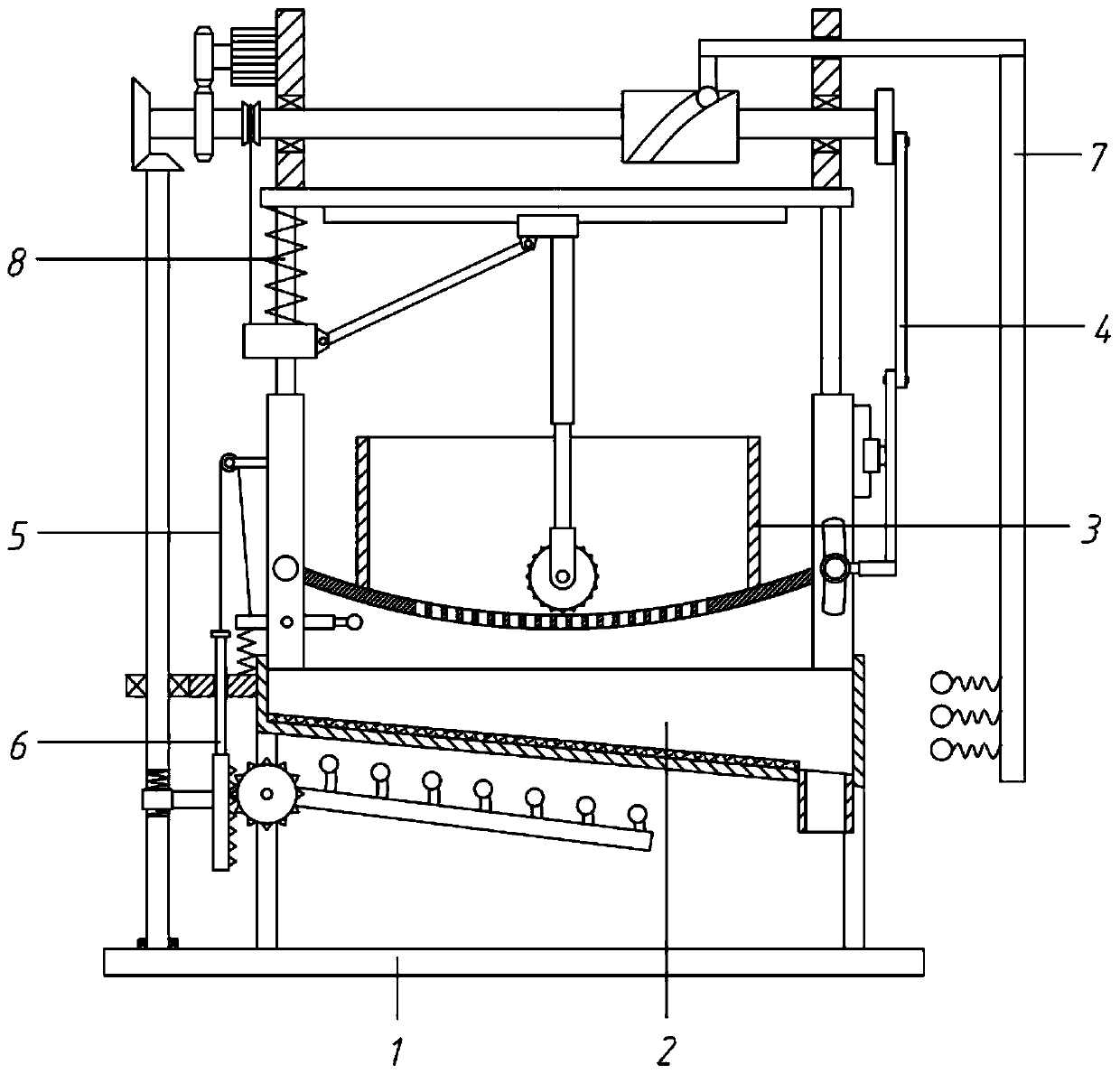
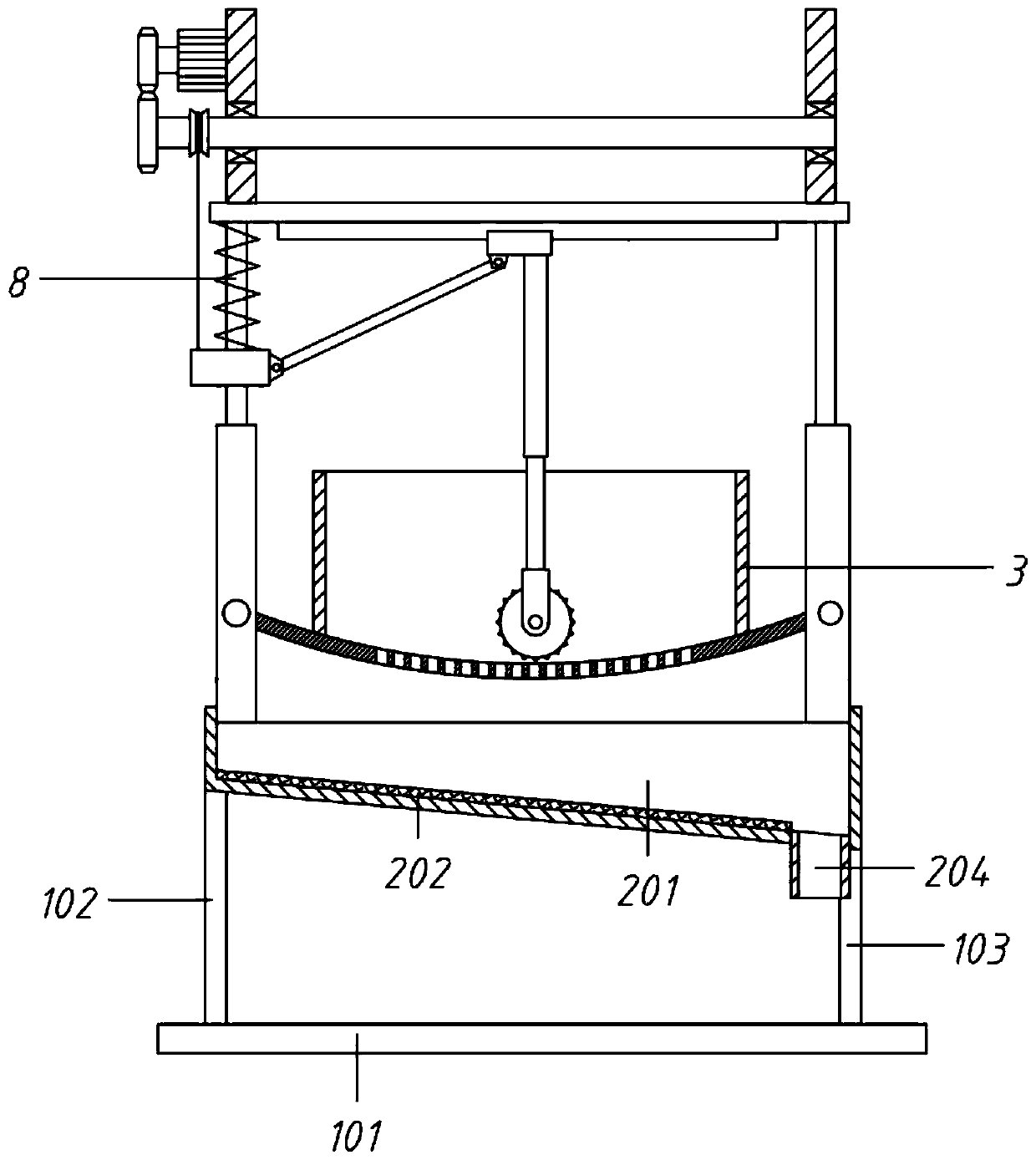
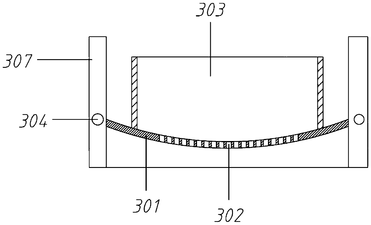
[0063] An impurity separator for rare earth permanent magnet materials used in civil engineering, including a frame assembly 1, an impurity removal assembly 2, a material storage assembly 3 and a crushing assembly 8;

[0064] The frame assembly 1 includes a base 101, a left pole 102 and a right pole 103. The left pole 102 is vertically fixed on the left end of the base 101, and the right pole 103 is vertically fixed on the right end of the base 101; The top of the component 1; the material storage component 3 is arranged above the impurity removal component 2;

Embodiment 2

[0066] An impurity separator for rare earth permanent magnet materials used in civil engineering, including a frame assembly 1, an impurity removal assembly 2, a material storage assembly 3 and a crushing assembly 8;

[0067] The frame assembly 1 includes a base 101, a left pole 102 and a right pole 103. The left pole 102 is vertically fixed on the left end of the base 101, and the right pole 103 is vertically fixed on the right end of the base 101; The top of the component 1; the material storage component 3 is arranged above the impurity removal component 2;

[0068] Wherein, the impurity removal assembly 2 includes an impurity removal box 201, an electromagnetic chuck 202 and a feeding pipe 204;

[0069] The two ends of the miscellaneous removal box 201 are fixedly connected to the top of the left pole 102 and the top of the right pole 103 respectively; the top of the miscellaneous removal box 201 is provided with an opening; the bottom of the miscellaneous removal box 201 ...

Embodiment 3

[0078] On the basis of embodiment 2,

[0079] Also includes the lower vibration material assembly 6, the lower vibration material assembly 6 includes No. 1 bevel gear 601, No. 2 bevel gear 602, No. 2 rotating shaft 603, support seat 604, reciprocating thread 606, moving nut 607, rack 608, guide rod 609 , limit block 610, driven gear 611, No. 1 rocker 612, installation rod 613 and No. 1 collision end 614;

[0080] The left end of No. 1 rotating shaft 807 passes through the left side plate 801 and is equipped with No. 1 bevel gear 601. No. 1 bevel gear 601 is vertically meshed with No. 2 bevel gear 602, and No. 2 bevel gear 602 is installed on the top of No. 2 rotating shaft 603; The left side of the box 201 is connected with a support seat 604, the second rotating shaft 603 passes downwards and rotates to connect to the supporting seat 604, and the bottom end of the second rotating shaft 603 rotates to connect with the base 101; the second rotating shaft 603 is processed with a r...


PUM


Abstract

The invention relates to the technical field of impurity separation equipment for rare earth permanent magnetic materials, and in particular to an impurity separator for rare earth permanent magneticmaterials for civil engineering. A servo motor rotates a first rotating shaft through gear rotation, so that a reel rotates along with the first rotating shaft to tighten or loosen a first pull rope.A sliding sleeve is moved up and down under the effect of the first pull rope and a first spring, and moves a first sliding block through a rotating rod, so that a first spring rod moves a crushing roller to crush the materials. Impurities and magnetic materials are separated, the crushed materials fall into an impurity removal box from a through hole. Magnetic adsorption is generated by using anelectromagnetic chuck such that the magnetic parts in the materials falling into the impurity removal box are adsorbed, and nonmagnetic impurities are automatically guided to the right end along withthe gradient of an inclined plane and are discharged from a discharge pipe. The impurity separator is easy and convenient to operate, and good in impurity removal effect.

Description

technical field [0001] The invention relates to the technical field of impurity separation equipment for rare earth permanent magnet materials, in particular to an impurity separator for rare earth permanent magnet materials used in civil engineering. Background technique [0002] Civil engineering refers to various technical work such as survey, planning, design, construction, installation and maintenance for new construction, reconstruction or expansion of buildings, structures and related supporting facilities, etc. engineering entities. [0003] Rare earth engineering is a direction and branch of civil engineering. The rare earth is a permanent magnetic material, which refers to a material that can maintain a constant magnetic field once it is magnetized. In practice, permanent magnet materials work in the second quadrant demagnetization part of the hysteresis loop after deep magnetic saturation and magnetization. Commonly used permanent magnet materials are divided in...

Claims


Application Information

Patent Timeline
Patent Type & Authority Applications(China)
IPC IPC(8): B02C4/26B02C4/42B02C4/28B02C23/10B65D88/66B07B1/54
CPCB02C4/26B02C4/28B02C4/42B02C23/10B07B1/54B65D88/66
Inventor 王俊龚剑孙驰赵雯雯
Owner ZHENGZHOU INST OF TECH
Learn More