an aircraft

A technology for aircraft and fuselage, which is applied in the field of aircraft, can solve problems such as blade occupancy, fuselage strengthening strength, applicability, and reduced flexibility, and achieve the effects of reducing air resistance, strengthening stability, and reducing requirements

Active Publication Date: 2021-07-27
广东梵亚科技有限公司
View PDF0 Cites 0 Cited by
  • Summary
  • Abstract
  • Description
  • Claims
  • Application Information

AI Technical Summary

Problems solved by technology

[0006] 1. The larger the propellers, the greater the torque and the strength of the fuselage needs to be strengthened
[0007] 2. The blades take up a lot of space and the installation position is low from the ground. The blades are easy to hit debris and be damaged during vertical take-off and landing or forced landing in the field.
[0008] 3. After the blades complete the vertical takeoff and stop working, the blades will rotate due to wind resistance, resulting in resistance and torque that will affect the maneuverability of the aircraft.
[0009] 4. Impossible or unfavorable for aircraft roll take-off, short take-off and landing
Reduced applicability and flexibility
[0010] 5. In the event of an emergency rescue, the tail propeller responds slowly and suddenly rotates at a high speed at a high speed, and the aircraft may disintegrate.
[0011] 6. The fuselage is integrated, it is not easy to replace other loads, and the expansion and diversification is insufficient

Method used


Image

  • an aircraft
  • an aircraft
  • an aircraft

Examples


Embodiment 1

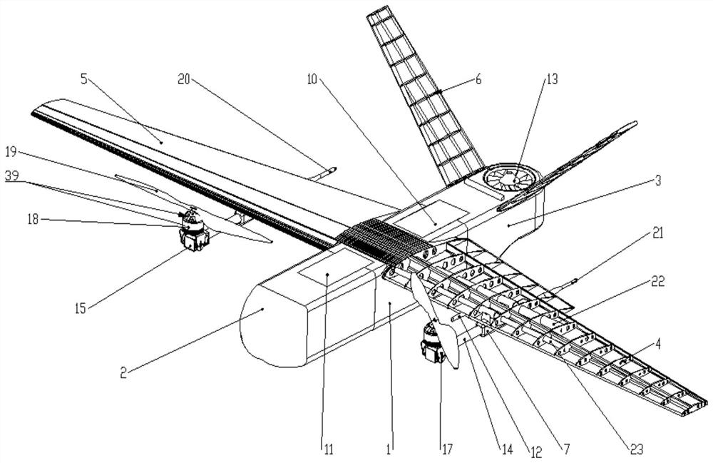
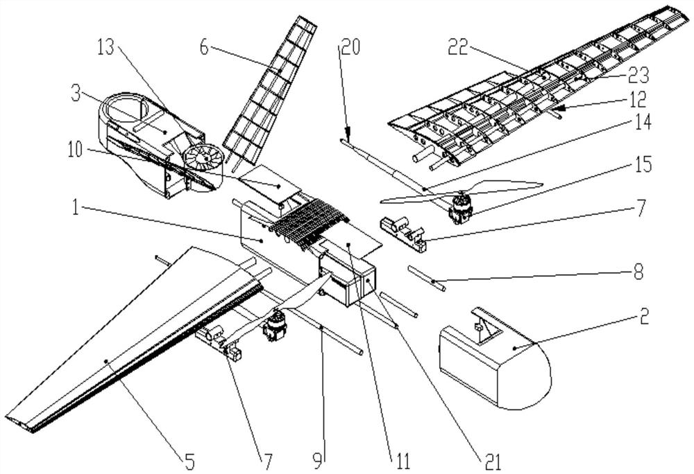
[0054] This embodiment provides an aircraft, comprising a fuselage, and wing assemblies arranged on both sides of the fuselage. The wing assembly includes the wing 5 and the tilting power assembly 39 arranged on the wing 5, and the wing assembly also includes a V-shaped empennage 6 arranged on the rear section 3 of the fuselage; the rear section 3 of the fuselage is set There is a detachable tail duct 13, which is provided with a tail duct motor inside the tail duct 13; this aircraft has a wingspan of 1740 (unit: millimeter mm, the same below), and a fuselage length of 834. A main wing with a length of 800 and a trapezoidal layout adopts the Clark-x airfoil inner and outer wing chord lengths of 250 and 150, and the wing angle of attack is 3°. The wing ribs are laminates with a thickness of 1mm. The 15 ribs are arranged equidistantly in sequence. Four 4*4 Paulownia wing beams are connected in groups of two to form the main and auxiliary beams of the wing. The main beam is locat...

Embodiment 2

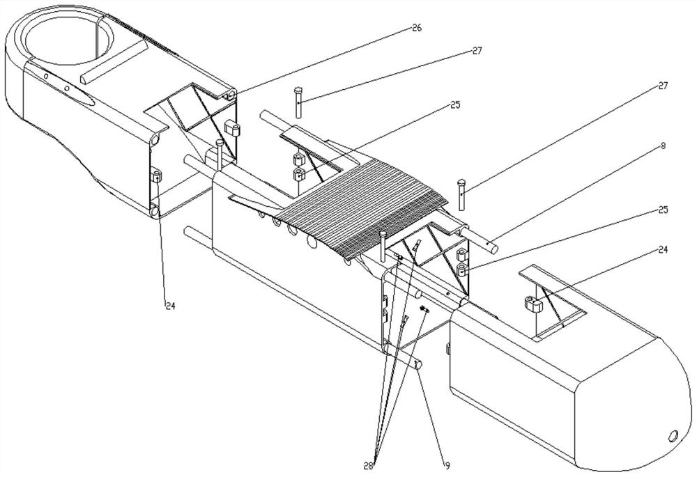
[0060] This embodiment is further optimized on the basis of Embodiment 1. Specifically, there is an R5 through hole that is consistent with the length of the middle section of the fuselage at the rounded corners on both sides of the bottom side of the middle section of the fuselage, and the R5mm hole that runs through the three sections of the fuselage. The carbon tubes form an interference fit. After the two carbon tubes at the bottom pass through the middle fuselage, there is an M5 screw hole passing through the center of the rounded corner at a distance of 20 from the front and back of the middle fuselage (the front refers to the direction of the machine head). One carbon tube There are two M5 screws at the front and back, and two carbon tubes on the bottom side of the middle fuselage, so there are four M3 screws in total to fix the carbon tube and the middle of the fuselage. There are R5 through holes with a length of 40 in the front and rear rounded corners of the middle s...

Embodiment 3

[0062]This embodiment is further optimized on the basis of embodiment 2. Specifically, there are R5 through holes of different lengths at the four rounded corners inside the front and rear sections of the fuselage, which form a clearance fit with the carbon tubes in the middle section of the fuselage. , and there is a protruding tenon in the middle of the opening of the front and rear sections of the fuselage. The front and rear sections of the fuselage can be slid in through the carbon tube. The three sections of the fuselage section are closed, and the bolts in the mortise and tenon structure enter the fuselage through the front and rear covers Internal and inserted in the mortise and tenon structure to form an interference fit in the section between the three sections of the fuselage. Thereby the three sections of the fuselage form a closed, firm and smooth integral fuselage. The mortise and tenon pin tube hole structure avoids the sliding of the front and rear sections of ...


PUM


Abstract

The invention discloses an aircraft, which belongs to a multifunctional unmanned aerial vehicle in the technical field of unmanned aerial vehicles. Disassemble the connected fuselage front section, fuselage middle section and fuselage rear section, the wing assembly includes wings and tilting power assemblies arranged on the wings, and the wing assembly also includes a V set at the rear end of the fuselage type empennage; the rear section of the fuselage is provided with a detachable tail duct, and the interior of the tail duct is provided with a tail duct motor; the invention provides an aircraft, which has a stronger expansion space and a wider range of use and adaptation wide.

Description

technical field [0001] The invention relates to the technical field of unmanned aerial vehicles, in particular to an aircraft. Background technique [0002] Most of the existing vertical take-off and landing tilting power module UAVs adopt the composite type or the tilting rotor type to realize the switching between the multi-rotor power and the tilting power module power. The existing tilt-rotor Y3 configuration vertical take-off and landing UAV, three motors are distributed in a Y shape, the left and right two motors in front of the wing can generate vector pulling force, and one motor at the tail is fixed, or all three motors can generate vector pulling force. [0003] 1. Vertical take-off and landing tilting power component UAV is a new trend of UAV industry in recent years. The flight form of tilting power components is currently the most efficient flight mode mastered by humans, but it often requires sliding takeoff or catapult takeoff. Vertical take-off and landing ...

Claims


Application Information

Patent Timeline
Patent Type & Authority Patents(China)
IPC IPC(8): B64C1/00B64C27/22B64C27/20
CPCB64C1/00B64C27/20B64C27/22
Inventor 彭振根
Owner 广东梵亚科技有限公司
Why Eureka
Try Eureka