Pressure vessel with pollution discharge buffer device

A technology of pressure vessel and buffer device, which is applied in the field of pressure vessel to prevent pollution and ensure personal safety.

Inactive Publication Date: 2020-04-03
山东华舜重工集团有限公司
View PDF16 Cites 1 Cited by
  • Summary
  • Abstract
  • Description
  • Claims
  • Application Information

AI Technical Summary

Problems solved by technology

Through the way of intermittent discharge, the discharge of the accumulated liquid in the pressure vessel is converted from under pressure to normal pressure, so as to fundamentally solve the problem of the discharge and splash of the accumulated liquid in the pressure vessel, and play the role of pressure buffer to prevent the discharge of the accumulated liquid from splashing To the ground to cause pollution, to ensure the personal safety of the operator during the operation

Method used


Image

  • Pressure vessel with pollution discharge buffer device
  • Pressure vessel with pollution discharge buffer device
  • Pressure vessel with pollution discharge buffer device

Examples


Embodiment 1

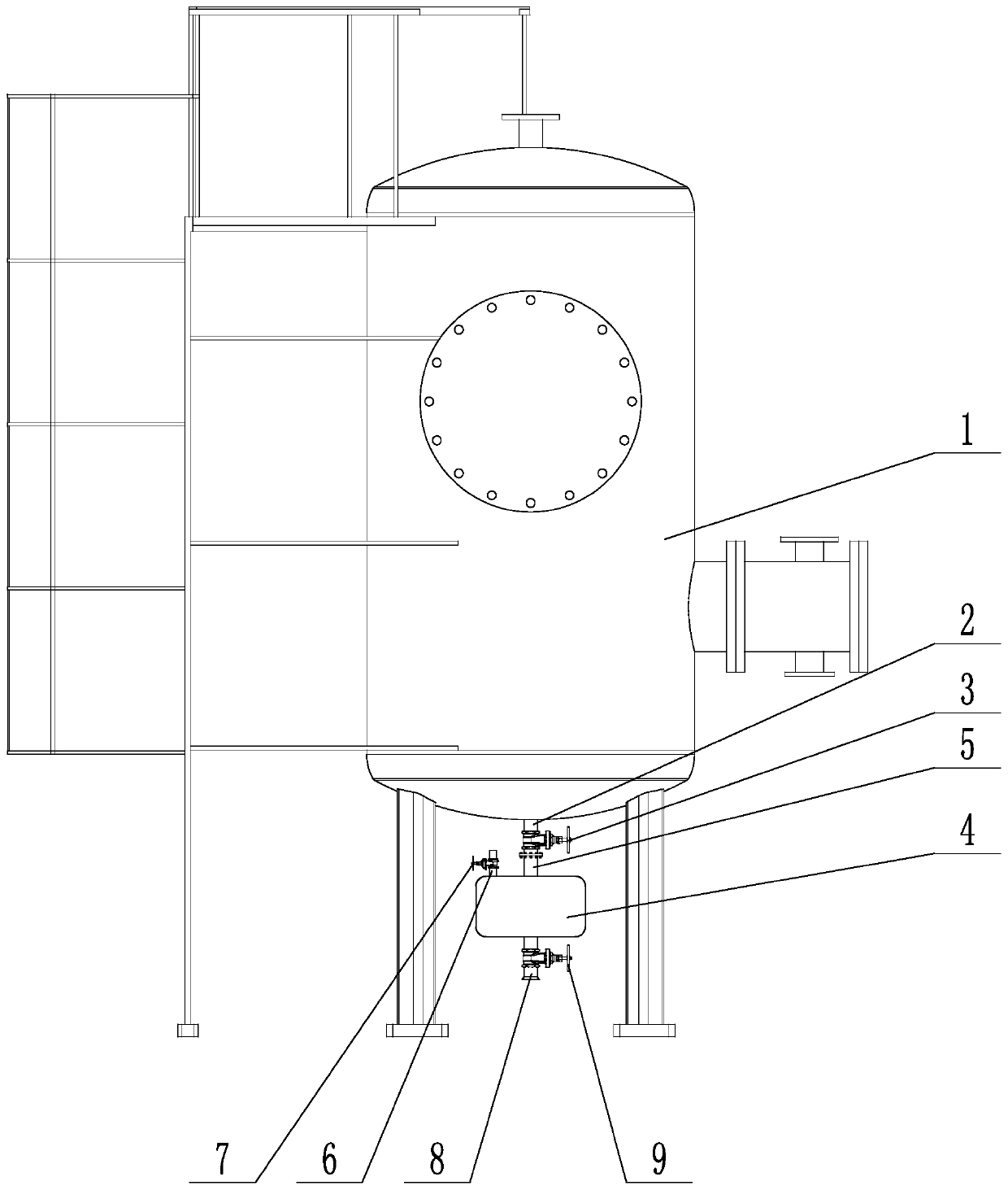
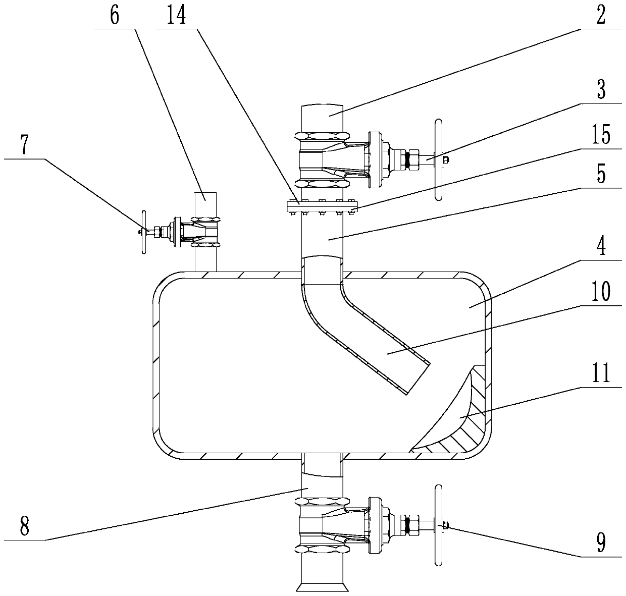
[0038] as attached figure 1 As shown, this embodiment takes a vertical gas pressure vessel as an example, a pressure vessel with a sewage buffer device, including a vessel body 1, and the pressure vessel is fixed on the ground through a frame body. A slag discharge pipe 2 is welded at the bottom of the container body 1 , and the slag discharge pipe communicates with the container body 1 . The slag discharge pipe 2 is connected in series with a first valve 3, and the bottom of the slag discharge pipe 2 is detachably and fixedly connected to a buffer tank 4, and the buffer tank can withstand the internal pressure of the pressure vessel. A centrally welded receiving pipe 5 on the top of the buffer tank 4 is used to connect with the slag discharge pipe 2. In this embodiment, the container body 1 and the buffer tank 4 are connected by sealing flanges. The bottom of the slag discharge pipe 2 is welded with a first flange 14, and the top of the receiving pipe 5 is welded with a seco...

Embodiment 1

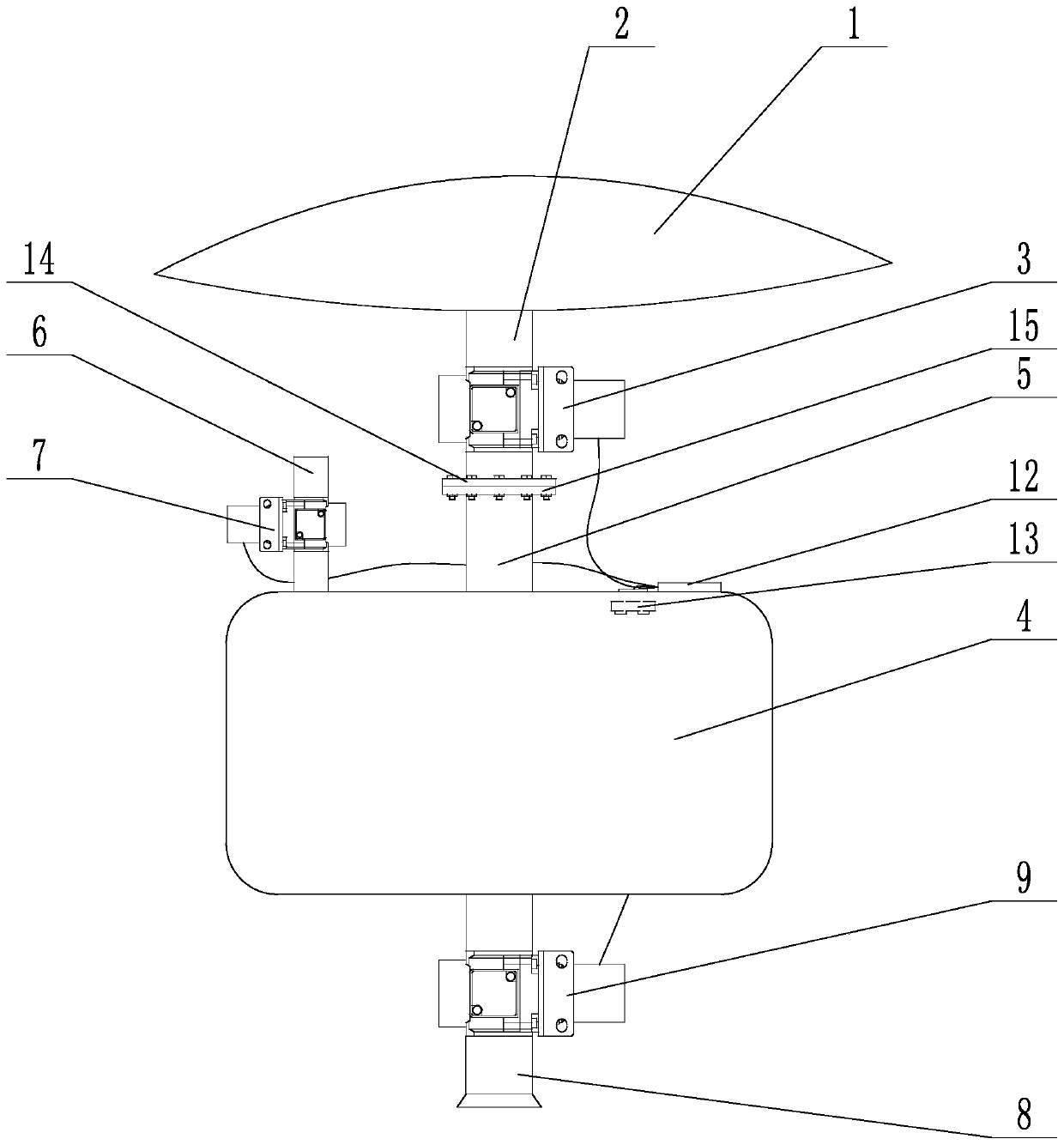
[0041] For Embodiment 1, the first valve 3, the pressure relief valve 7, and the second valve 9 described in this embodiment are all solenoid valves, and the device further includes a controller, which is a single-chip microcomputer, which is connected to the single-chip microcomputer. Action control switch. The action control switch is used as a start signal for the single-chip microcomputer to control the cyclic actions of a plurality of solenoid valves. The single-chip microcomputer and the solenoid valve are powered by a DC power supply, and the first valve 3 , the pressure relief valve 7 , and the second valve 9 are all connected to the controller 12 by signal. In this embodiment, in order to ensure the stability of the pressure vessel, a manual valve can be connected in series above the first valve, so as to reduce the pressure impact on the first valve. In the device, the first valve, the second valve and the pressure relief valve are controlled by the single-chip micr...

Embodiment 2

[0044] For Embodiment 2, in this embodiment, the buffer tank 4 is provided with a sensor 13 , and the sensor 13 is signally connected to the controller 12 . The sensor 13 is a pressure sensor and / or a liquid level sensor. The pressure sensor is arranged on the inner top wall of the buffer tank, and the liquid level sensor adopts a photoelectric liquid level sensor. In order to facilitate the installation of the sensor, a wire hole is provided on the top of the buffer tank, and after the wire hole passes through the signal wire, it is sealed with a high-pressure sealant.


PUM


Abstract

The invention provides a pressure vessel with a pollution discharge buffer device, and mainly relates to the field of pressure vessels. The pressure vessel with the pollution discharge buffer device comprises a vessel body, wherein the bottom of the vessel body is provided with a slag discharge pipe, the slag discharge pipe is provided with a first valve, the bottom of the slag discharge pipe is detachably and fixedly connected with a buffer tank, an adapting pipe is arranged in the center of the top of the buffer tank, a pressure relief pipe is arranged on one side of the top surface of the buffer tank, the pressure relief pipe is provided with a pressure relief valve, the bottom of the buffer tank is provided with a leading-out pipe, the leading-out pipe is provided with a second valve,the top in the buffer tank is provided with a guide pipe communicated with the adapting pipe, and one side of the bottom of the buffer tank is provided with a pressure bearing wall. The pressure vessel has the beneficial effects that the discharge of an accumulated liquid in the pressure vessel is converted into normal pressure from under pressure by means of intermittent discharge, the accumulated liquid is prevented from being splashed to the ground to result in pollution, and the personal safety of operators in the operation process is guaranteed.

Description

technical field [0001] The invention mainly relates to the field of pressure vessels, in particular to a pressure vessel with a blowdown buffer device. Background technique [0002] Pressure vessels are widely used in petrochemical, power station equipment, logistics storage and transportation and other fields, because the storage and transportation of pressure vessels are pressurized gas or liquid. Under the pressure environment, liquid (mainly water) will gradually precipitate in the gas pressure vessel. If it is not cleaned for a long time, the inner wall of the pressure vessel will be eroded, the volume will be reduced, and the safety of storage and transportation of materials will be harmed. At present, workers are required to regularly overhaul and discharge pressure vessels to ensure the normal use of pressure vessels and prolong their service life. [0003] However, when the pressure vessel is discharged, because the discharge process is carried out under pressure, ...

Claims


Application Information

Patent Timeline
Patent Type & Authority Applications(China)
IPC IPC(8): F16J12/00
CPCF16J12/00
Inventor 李俊才吴雪飞张军李慧钱占顺张凯
Owner 山东华舜重工集团有限公司
Why Eureka
Try Eureka