Intraocular display device based on retinal scanning

A retinal scanning and display device technology, applied in static indicators, glasses/goggles, optics, etc., can solve the problem of inability to achieve foveal imaging, inability to fundamentally solve the time delay of high-resolution image processing and device power consumption and other problems, to achieve the effect of reducing the total number of pixels, reducing system complexity, and reducing device power consumption

Active Publication Date: 2020-04-03
SHANGHAI JIAO TONG UNIV
View PDF5 Cites 4 Cited by
  • Summary
  • Abstract
  • Description
  • Claims
  • Application Information

AI Technical Summary

Problems solved by technology

[0005] The existing disclosed retinal scanning devices cannot achieve foveated imaging without an additional human eye tracking device
Even with the addition of

Method used


Image

  • Intraocular display device based on retinal scanning
  • Intraocular display device based on retinal scanning

Examples


Embodiment Construction

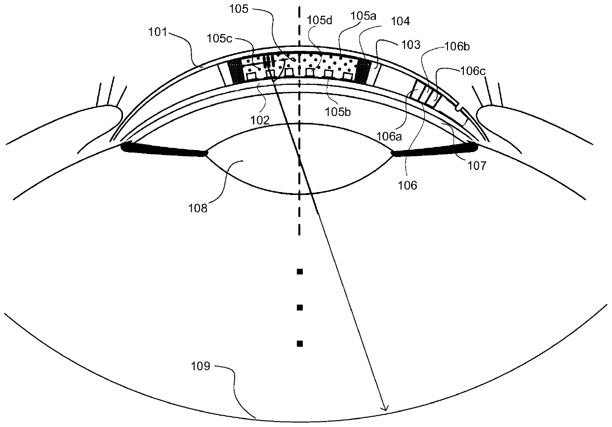
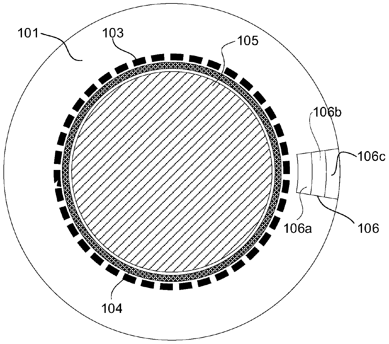
[0017] Such as figure 1 with figure 2 As shown, the intraocular display device based on retinal scanning shown in this embodiment includes: a first flexible substrate 101 on the same side as the eyelid of the human eye, a second flexible substrate 102 on the same side as the cornea of ​​the human eye, and a light emitting substrate disposed therebetween. Diode array 103, light collimator 104, electrically controlled liquid crystal grating 105 for adjusting light direction, and control unit 106, wherein: the light-emitting end face of light emitting diode array 103 is connected with light collimator 104, and control unit 106 is connected with light emitting diode The array 103 is connected to an electrically controlled liquid crystal grating 105 .

[0018] The LED array 103 is an annular array composed of a plurality of LEDs, and the number of LEDs Where: R is the radius of the eyeball, D is the diameter of the cone cells, ρ is the density of the cone cells, and x is the ec...


PUM


Abstract

The invention discloses an intraocular display device based on retinal scanning. The device comprises a first flexible substrate on the same side as an eyelid, a second flexible substrate on the sameside as a cornea, a light emitting diode array arranged between the first flexible substrate and the second flexible substrate, a light collimator, an electric control liquid crystal grating used foradjusting the light direction, and a control unit. The light emitting diode array is connected with the light collimator, and the control unit is connected with the light emitting diode array and theelectric control liquid crystal grating and receives and transmits image information and light angle information; the device is worn on the cornea of a human eye, so that exit pupil enlargement and human eye tracking are not needed, and the system complexity is simplified; by matching the number of the light-emitting diodes with the cone cell density, central concave imaging is achieved in an annular scanning mode, and The invention has the advantages that the highest angular resolution of human eyes is met. The total pixel number is reduced, and the time delay and device power consumption forprocessing high-resolution images are reduced. The invention is suitable for the intelligent contact lenses oriented to augmented reality, virtual reality and mixed reality.

Description

technical field [0001] The present invention relates to a technology in the field of wearable devices, in particular to an intraocular display device based on retinal scanning. Background technique [0002] In recent years, with the rise of augmented reality and virtual reality concepts, near-eye display (Near-Eye Display, NED for short) technology has become the focus of the current display field. Since American Ivan Sutherland invented the first near-eye display in 1968, countless near-eye display solutions have emerged, including: (1) near-eye display based on beam combiner; (2) near-eye display based on waveguide; (3) ) near-eye display based on retinal projection. The former two form a virtual image through a beam combiner or a waveguide, and then view the virtual image with human eyes. The problem is that the optical path is complicated and the field of view (Field of View, FOV) is small. Retinal projection directly projects images on the retina, which has the advant...

Claims


Application Information

Patent Timeline
IPC IPC(8): G02C7/04G02F1/1335G02F1/1343G02F1/133
CPCG02C7/049G02F1/13306G02F1/133504G02F1/134309
Inventor 陈超平陈捷刘浩文姜婧辉米岚田
Owner SHANGHAI JIAO TONG UNIV
Why Eureka
Try Eureka