Equipment and process for coating liquid crystal film on basis of TAC base material

A technology of substrate coating and coating equipment, which is applied to the device for coating liquid on the surface, coating, pretreatment surface, etc. Simple, highly automated, long service life

Inactive Publication Date: 2020-04-07
SUZHOU HAOLI CULTURE MEDIA TECH CO LTD
View PDF12 Cites 4 Cited by
  • Summary
  • Abstract
  • Description
  • Claims
  • Application Information

AI Technical Summary

Problems solved by technology

[0002] TAC is an important material in the production process of TN-type display panels. Although in the history of the development of polarizers, as long as transparent plastics appeared, it was tried to replace TAC, but none of them could exceed the light penetration of TAC above 93%, and TAC It is a negative C-plate itself. Different formulas and degrees of esterification affect the phase difference. The current phase difference is about 30~200nm. It has a specific compensation ability for liquid crystal displays, so although TAC has a water absorption rate High, dimensional stability and surface characteristics are easily affected by the environment, but none of them can be replaced by other materials
Although the TN type display has the advantages of cheap price and fast response time of panel liquid crystal molecules, it also has disadvantages such as phase delay. Discotic liquid crystal molecules have always played an important role in the application of liquid crystal displays and are widely used in optical compensation film materials. Among them, it can significantly improve the viewing angle of the TN type display panel
However, the process requirements for preparing optical compensation films using discotic liquid crystal materials are relatively high, the overall preparation process is complex, the investment in coating equipment is expensive, and there are many factors affecting coating quality, which have always been the constraints for large-scale production.

Method used


Image

  • Equipment and process for coating liquid crystal film on basis of TAC base material
  • Equipment and process for coating liquid crystal film on basis of TAC base material
  • Equipment and process for coating liquid crystal film on basis of TAC base material

Examples


Embodiment Construction

[0032] The present invention will be further explained below in conjunction with the accompanying drawings and specific embodiments.

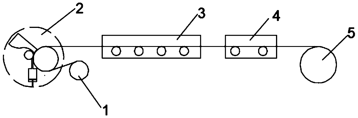
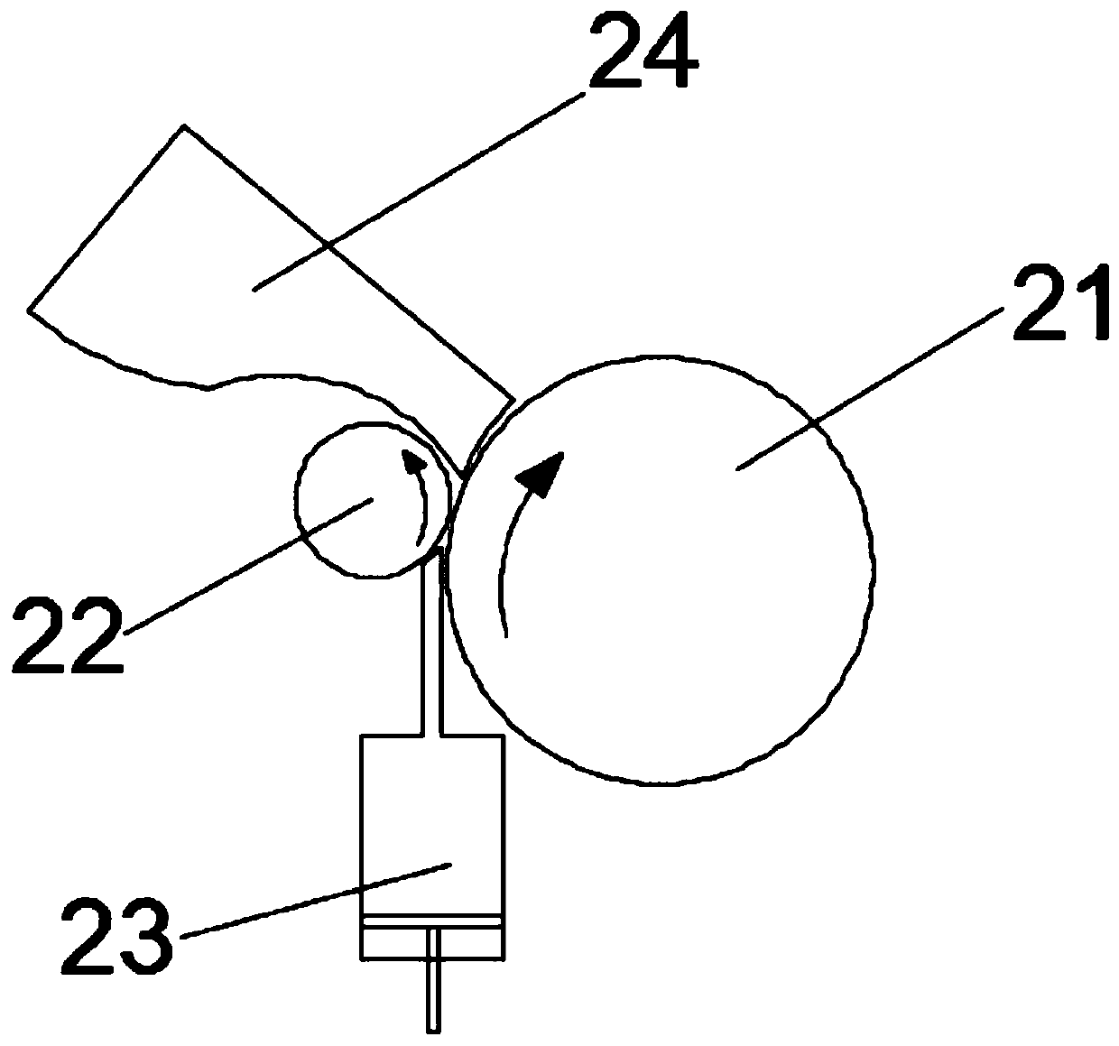
[0033] Such as figure 1 and figure 2 The shown coating equipment for coating liquid crystal film based on TAC substrate includes substrate roller 1, coating device 2, constant temperature drying oven 3, UV curing lamp 4 and finished coil roller 5, consisting of five A production line, the substrate roller 1 is used to carry the TAC substrate, the coating device 2 is located above the side of the substrate roller 1, and is used to evenly coat the liquid crystal material on the TAC substrate, the The coating device 2 comprises a feed roller 21, a coating roller 22, a coating liquid supply device 23 and a scraper 24, the feed roller 21 is located at the output end of the substrate roller 1, and the coating roller 22 is located at The left side of the feed roller 21 forms a coating gap with the feed roller 21, the coating liquid supply device 23...


PUM


Abstract

The invention discloses coating equipment for coating a liquid crystal film on the basis of a TAC base material. The equipment comprises a base material roller, a coating device, a constant-temperature drying box, a UV curing lamp and a finished coiled material roller, wherein the five parts form a production line; the base material roller is used for bearing the TAC base material; the coating device comprises a feeding roller, a coating roller, a coating liquid supply device and a scraper; the constant-temperature drying box is located at the output end of the coating device; the UV curing lamp is located at the output end of the constant-temperature drying box and is used for curing liquid crystals; and the finished product coiled material roller is used for winding a coated finished product. The invention further discloses a production process for coating a liquid crystal film the basis of a TAC base material by utilizing the equipment. The coating equipment and process for coatingthe liquid crystal film on the basis of the TAC base material have the advantages of simple mechanism, high coating precision and convenience in large-scale production.

Description

technical field [0001] The invention belongs to the field of optical materials, and in particular relates to a device and a process for coating a liquid crystal film based on a TAC substrate. Background technique [0002] TAC is an important material in the production process of TN-type display panels. Although in the history of the development of polarizers, as long as transparent plastics appeared, it was tried to replace TAC, but none of them could exceed the light penetration of TAC above 93%, and TAC It is a negative C-plate itself. Different formulas and degrees of esterification affect the phase difference. The current phase difference is about 30~200nm. It has a specific compensation ability for liquid crystal displays, so although TAC has a water absorption rate High, dimensional stability and surface characteristics are vulnerable to environmental influences, but none of them can be replaced by other materials. Although the TN type display has the advantages of ch...

Claims


Application Information

Patent Timeline
Patent Type & Authority Applications(China)
IPC IPC(8): B05C1/08B05C9/14B05C11/10B05C11/04B05D3/02B05D3/06B05D7/24
CPCB05C1/0813B05C1/0826B05C9/14B05C11/045B05C11/1002B05D3/0254B05D3/067B05D7/24
Inventor 孙东伟
Owner SUZHOU HAOLI CULTURE MEDIA TECH CO LTD
Why Eureka
Try Eureka