Remediation device for soil contamination

A soil pollution and soil technology, applied in the field of soil remediation, can solve the problems of low soil treatment efficiency, unfavorable operation, complicated mechanical structure, etc., and achieve the effect of low treatment cost, reduced remediation cost and high remediation efficiency

Inactive Publication Date: 2020-04-07
上海景域园林建设发展有限公司
4 Cites 0 Cited by

AI-Extracted Technical Summary

Problems solved by technology

[0007] The above devices all use mechanical structures for soil pollution remediation, and the common problems are: 1. The...

Method used

In the present invention, the liquid injection drainage plate 2 and the liquid extraction drainage plate 3 are simultaneously used as electrodes inserted into the polluted soil area. After the power supply is connected to the DC power supply, the liquid injection drainage plate 2 and the liquid extraction drainage plate 3 are all charged, and the electric field is used to Various electrokinetic effects such as electrophoresis, electroosmosis, etc., drive soil pollutants to migrate directionally along the direction of the electric field, that is, pollutants are enriched to the pumping and draining plate 3, and then can be efficiently discharged through the pumping and draining plate 3. Therefore, the present invention utilizes the principle of electrodynamic restoration to enhance the enrichment effect of pollutants at the liquid pumping and draining plate, thereby improving the removal effect of pollutants.
The in-situ soil pollution remediation device provided by the present invention adopts the combined mode of electrodynamic repair, artificial freezing and shaft leaching to repair clay heavy metal contaminated soil in situ without excavating polluted soil, in-situ remediation,...

Abstract

The invention relates to a remediation device for soil contamination. The remediation device is used for in-situ remediation of soil and comprises a power supply, a refrigerator, a liquid injection pump, a vacuum pump, a steam-water separator and a freezing-thawing and leaching unit, wherein the freezing-thawing and leaching unit comprises two liquid injecting and water draining plates, two liquidpumping and water draining plates and a freezing pipe; the two liquid pumping and water draining plates are arranged on the outer sides of the freezing pipe; the two liquid injecting and water draining plates are symmetrically arranged on the outer sides of the liquid pumping and water draining plates; the refrigerator is connected to the freezing pipe; a liquid injecting pump is connected to theliquid injecting and water draining plates; the liquid pumping and water draining plates are connected to the steam-water separator; the steam-water separator is connected to the vacuum pump; the twoliquid injecting and water draining plates serve as anodes, and the two liquid pumping and water draining plates serve as cathodes; the liquid injecting and water draining plates and the liquid pumping and water draining plates which are located on the same side of the freezing pipe are connected with the positive electrode and the negative electrode of a power source through wires; and electrodeareas are formed between the liquid injecting and water draining plates and the liquid pumping and water draining plates. Compared with the prior art, the remediation effect of the remediation deviceis improved in the manner of a combination of electric remediation, manual freezing and vertical shaft leaching.

Application Domain

Contaminated soil reclamation

Technology Topic

In situ remediationAnode +7

Image

  • Remediation device for soil contamination

Examples

  • Experimental program(1)

Example Embodiment

[0035] Example
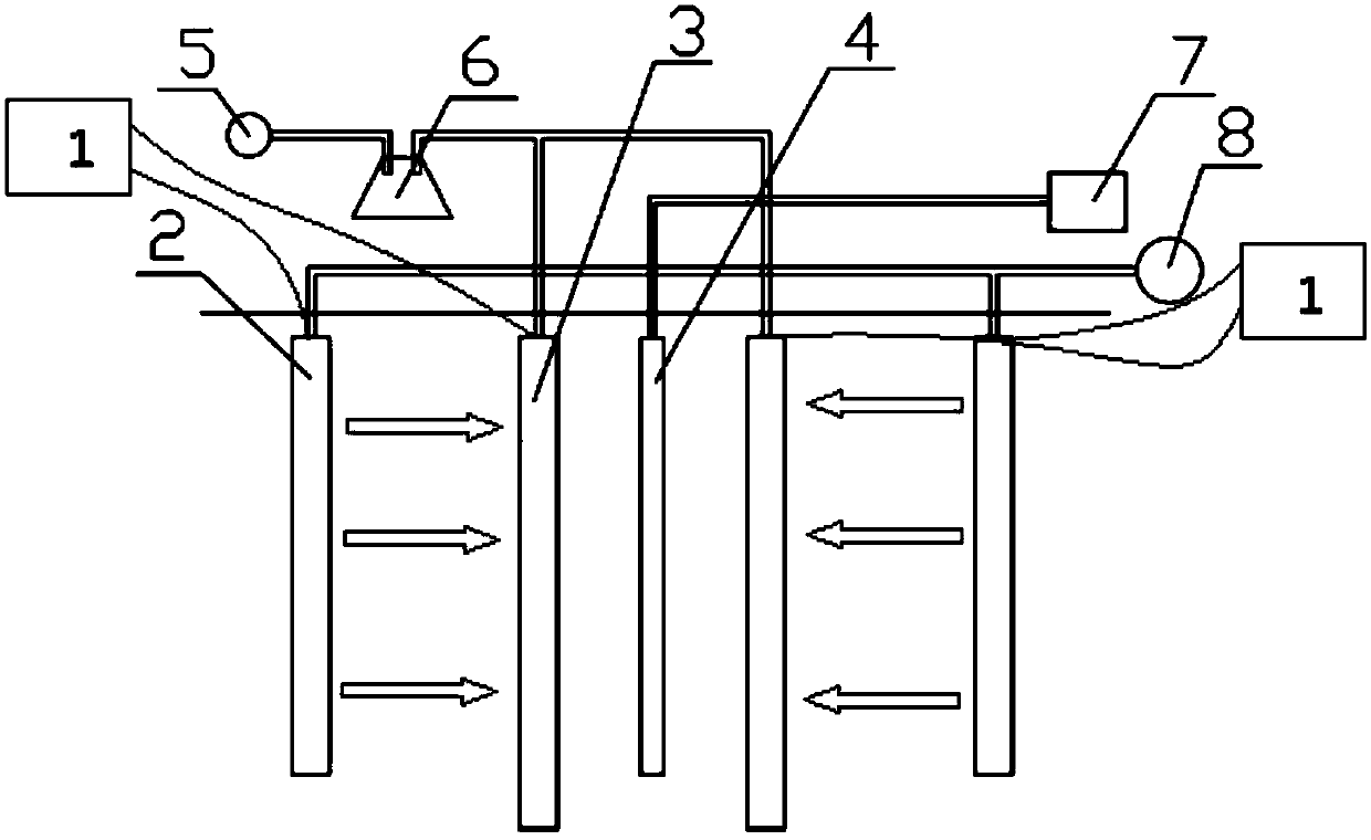
[0036] refer to figure 1, a soil pollution remediation device, which is a device for in-situ remediation of soil, the device includes a power supply 1, a freezer 7, a liquid injection pump 8, a vacuum pump 5, a steam-water separator 6 and a freeze-thaw rinse unit, the freeze-thaw rinse unit includes Two liquid injection and drainage plates 2, two liquid suction and drainage plates 3 and one freezing pipe 4, the two liquid suction and drainage plates 3 are symmetrically arranged on the outside of the freezing pipe 4 with the freezing pipe 4 as the center, and the two liquid injection and drainage plates 2 are The freezing pipe 4 is symmetrically arranged on the outside of the pumping and draining plate 3. The refrigerator 7 is connected to the freezing pipe 4 through a pipeline, and the liquid injection pump 8 is connected to the top of the liquid filling and draining plate 2 through a pipeline. The pipeline is connected to the steam-water separator 6, and the steam-water separator 6 is connected to the vacuum pump 5; the two liquid injection and drainage plates 2 are simultaneously used as anodes, and the two liquid suction and drainage plates 3 are simultaneously used as cathodes, and the liquid injection and drainage plates on the same side of the freezing tube 4 2 and the liquid suction and drainage plate 3 are connected to the positive and negative poles of the power supply 1 through wires, and an electrode area is formed between the liquid injection and drainage plate 2 and the liquid suction and drainage plate 3, figure 1 The direction of the middle arrow is the direction of current, which is also the direction of water flow.
[0037] Among them, several temperature sensors are also provided, and the temperature sensors are arranged at equal intervals between the freezing pipe 4 and the liquid injection and drainage plate 2 . The distance between the two temperature sensors is 2-5cm.
[0038] Wherein, the bottom end of the liquid injection and drainage plate 2 is 0.2-0.5 m higher than the bottom end of the liquid suction and drainage plate 3 . The distance between adjacent liquid injection and drainage plates 2 and liquid suction and drainage plates 3 is 0.1-0.2m. The liquid injection drainage plate 2 and the liquid extraction drainage plate 3 are both inert plate-shaped conductive plates, which are porous carbon plates, graphite plates or stainless steel plates. Power supply 1 applies a voltage of 0.5-5V.
[0039] Among them, the method of using the soil pollution remediation device includes the following steps:
[0040] 1 Select the type and concentration ratio of the eluent according to the soil pollution degree and soil physical and chemical properties of the repair site, prepare the eluent for use, and lay out pipelines and components at the repair site;
[0041] 2 Inject the eluent into the liquid injection and drainage plate at a constant speed through the liquid injection pump, and at the same time turn on the freezer and observe the progress of the 0°C isotherm in the soil through the temperature sensor to determine the advancing rate of the freezing front, and then adjust the temperature of the freezing tube through the freezer so that The migration rate of the freezing front is 0.5-12cm/d;
[0042] 3. When the freezing front moves slowly to 5-10cm beyond the pumping and draining plate, stop the freezer and circulate hot water into the freezing pipe to thaw the frozen soil;
[0043] 4 After the frozen soil is completely thawed, turn on the vacuum pump to adjust the vacuum negative pressure so that the liquid injection rate is the same as the pumping rate, and the leachate in the soil is pumped to the surface through the pumping and draining plate and collected in the steam-water separator. The leachate is recycled;
[0044] 5 Turn on the power supply, apply direct current to form an electric field, use various electrokinetic effects such as electrophoresis, electroosmosis, etc. generated by the electric field, to drive the soil pollutants to migrate directional along the direction of the electric field, that is, enriched to the pumping drainage plate, and then can be efficiently pumped Liquid drainage plate discharge;
[0045] 6. Analyze the soil for heavy metal residues. If it meets the soil environmental quality standard, stop the suction and the contaminated soil treatment is over; if it does not meet the soil environmental quality standard, repeat steps 2 to 5 until the tested soil meets the soil environmental quality standard .
[0046] The in-situ soil pollution remediation device provided by the present invention adopts a combination of electric repair, artificial freezing and shaft leaching to repair clayey heavy metal-contaminated soil in situ without excavating polluted soil. The current in-situ shaft leaching method has the problem of low leaching efficiency in low-permeability clay. The process is simple and the cost is low, which is conducive to popularization and application;
[0047] The present invention adds a freezing tube to the vertical shaft leaching method, utilizes the characteristics that the moisture on the unfrozen soil side migrates to the freezing front and the soil permeability increases due to freezing and thawing during artificial freezing, controls the temperature gradient of the soil to drive the water migration, and makes the leaching The liquid can fully contact with the pollutants adsorbed on the soil particles to improve the leaching effect; the freeze-thaw action destroys the original structure of the soil particles and rearranges the soil particles, which helps the eluent fully contact with the heavy metal pollutants in the soil and improves the washing effect. Leaching efficiency; repeated freezing and thawing can increase the soil permeability coefficient, which helps to improve the suction efficiency of the eluent in sticky soil, makes the eluent more fully contact with heavy metal ions, reduces the liquid-to-soil ratio, and is conducive to large-scale leaching wash.
[0048] In the present invention, the liquid injection and drainage plate 2 and the liquid suction and drainage plate 3 are simultaneously used as electrodes inserted into the polluted soil area. Electrokinetic effects such as electrophoresis, electroosmosis, etc., drive soil pollutants to migrate directionally along the direction of the electric field, that is, pollutants are enriched to the pumping and draining plate 3, and then can be efficiently discharged through the pumping and draining plate 3. Therefore, the present invention utilizes the principle of electrodynamic restoration to enhance the enrichment effect of pollutants at the liquid pumping and draining plate, thereby improving the removal effect of pollutants.

PUM

no PUM

Description & Claims & Application Information

We can also present the details of the Description, Claims and Application information to help users get a comprehensive understanding of the technical details of the patent, such as background art, summary of invention, brief description of drawings, description of embodiments, and other original content. On the other hand, users can also determine the specific scope of protection of the technology through the list of claims; as well as understand the changes in the life cycle of the technology with the presentation of the patent timeline. Login to view more.

Similar technology patents

Treating method for oily sludge

InactiveCN106957136AThe treatment method is simple and effectiveSimple process
Owner:安徽省通源环境节能股份有限公司

Preparation method of Apremilast

Owner:徐州鑫辉生物能源科技有限公司

Classification and recommendation of technical efficacy words

  • Simple process
  • Improve repair efficiency

Method for preparing graphite alkyne film

ActiveCN101774570ASimple processuniform surface
Owner:INST OF CHEM CHINESE ACAD OF SCI

Liquid crystal display and repairing method thereof

InactiveCN101592797AImprove repair efficiencyAvoid mutual short circuit
Owner:SHANGHAI SVA LIQUID CRYSTAL DISPLAY
Why Eureka
Try Eureka