Automatic identification method for welding area of welding workpiece, computer device and computer readable storage medium

A welding area and automatic identification technology, which is applied to computer parts, calculations, welding equipment, etc., can solve the problems that cannot meet the automatic production of small batches of aluminum templates, cannot automatically calculate the welding area of ​​welding workpieces, etc., and achieve reduction The amount of calculation of height coordinates, the effect of improving accuracy and welding quality, and reducing workload

Active Publication Date: 2020-04-07
珠海屏珠科技有限公司
View PDF6 Cites 4 Cited by
  • Summary
  • Abstract
  • Description
  • Claims
  • Application Information

AI Technical Summary

Problems solved by technology

However, these welding machines cannot automatically calculate the area to be welded on the welding workpiece, let alone automatically generate the motion trajectory of the welding equipment according to the calculated welding area. Therefore, the motion trajectory of the welding equipment needs to be preset, so that It cannot meet the requirements of automatic production of small batches of aluminum formwork

Method used


Image

  • Automatic identification method for welding area of welding workpiece, computer device and computer readable storage medium
  • Automatic identification method for welding area of welding workpiece, computer device and computer readable storage medium
  • Automatic identification method for welding area of welding workpiece, computer device and computer readable storage medium

Examples


no. 1 example

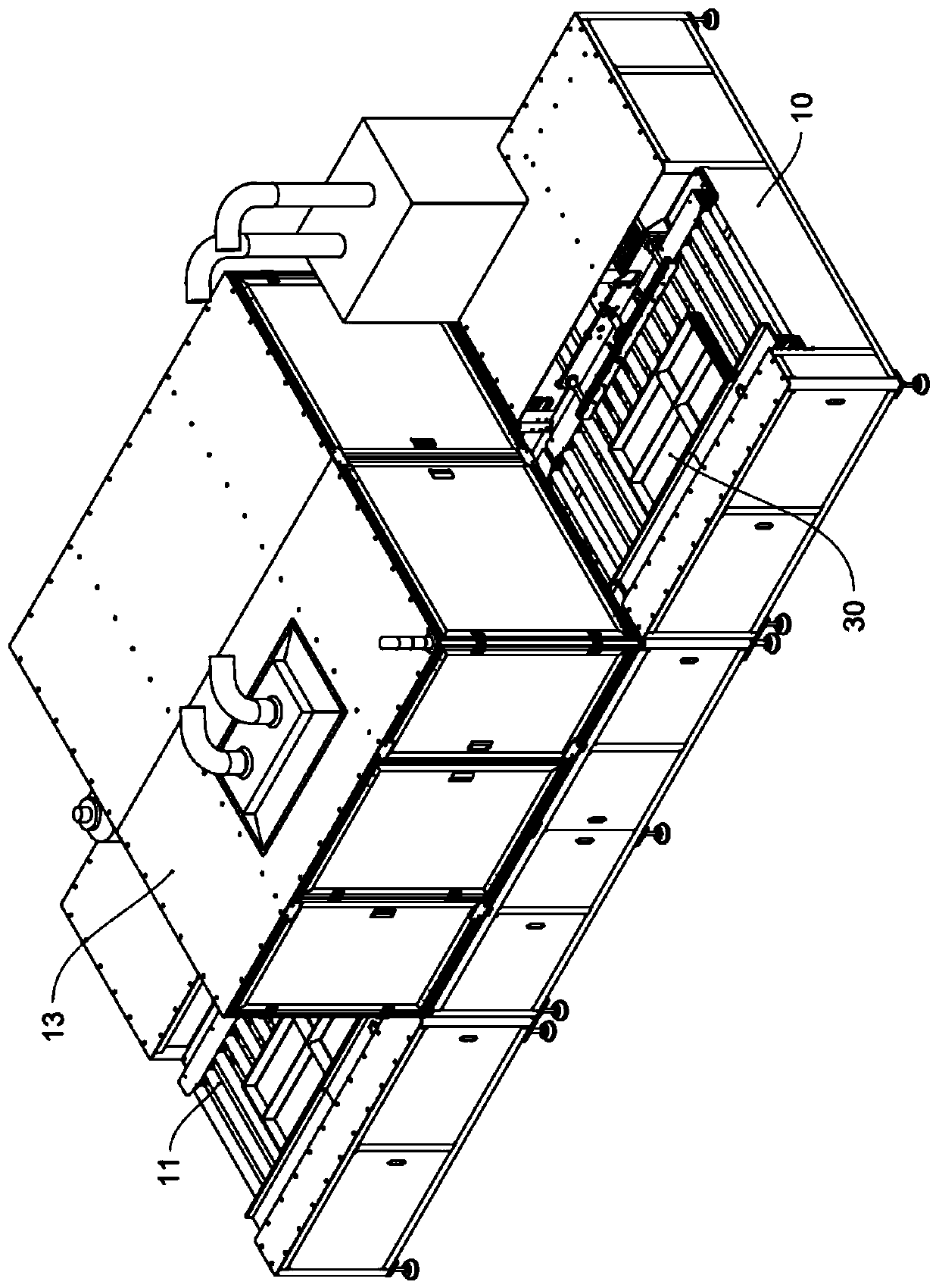
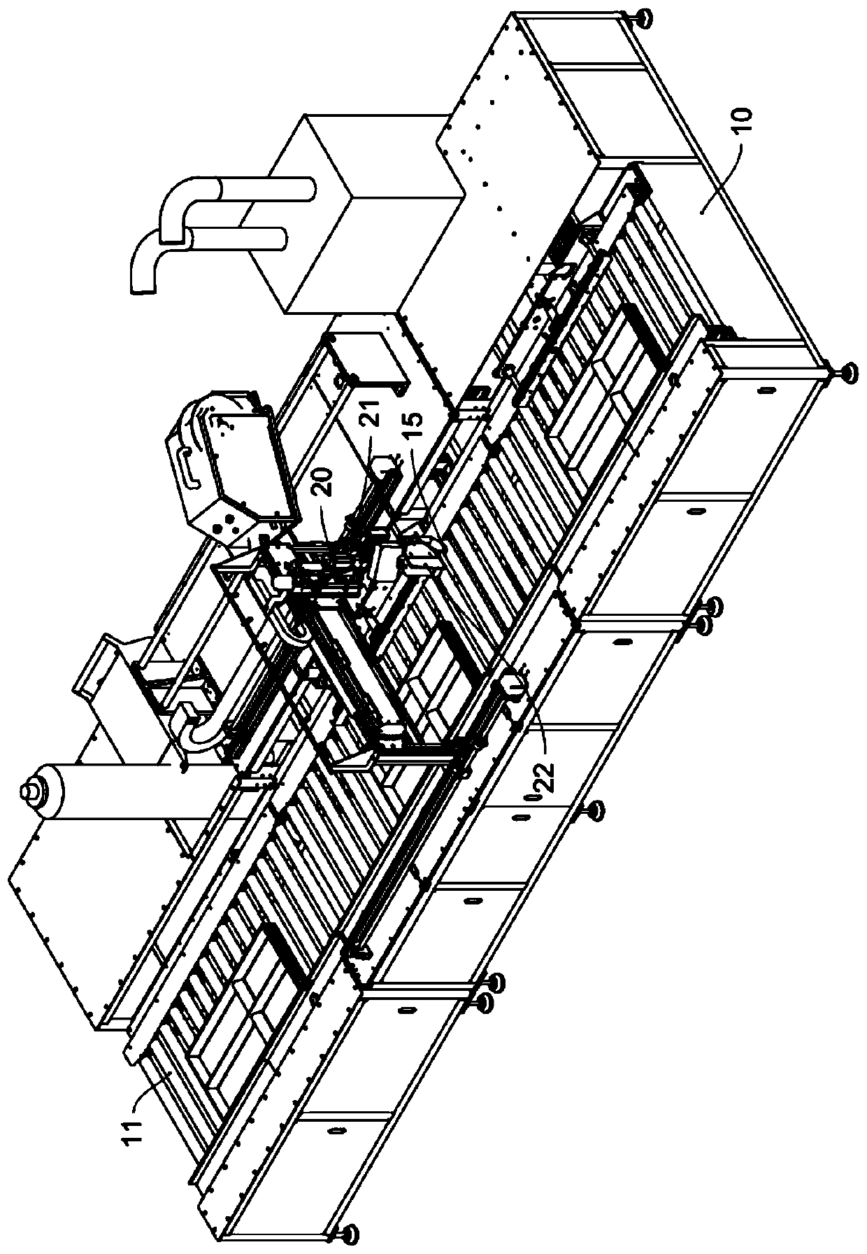
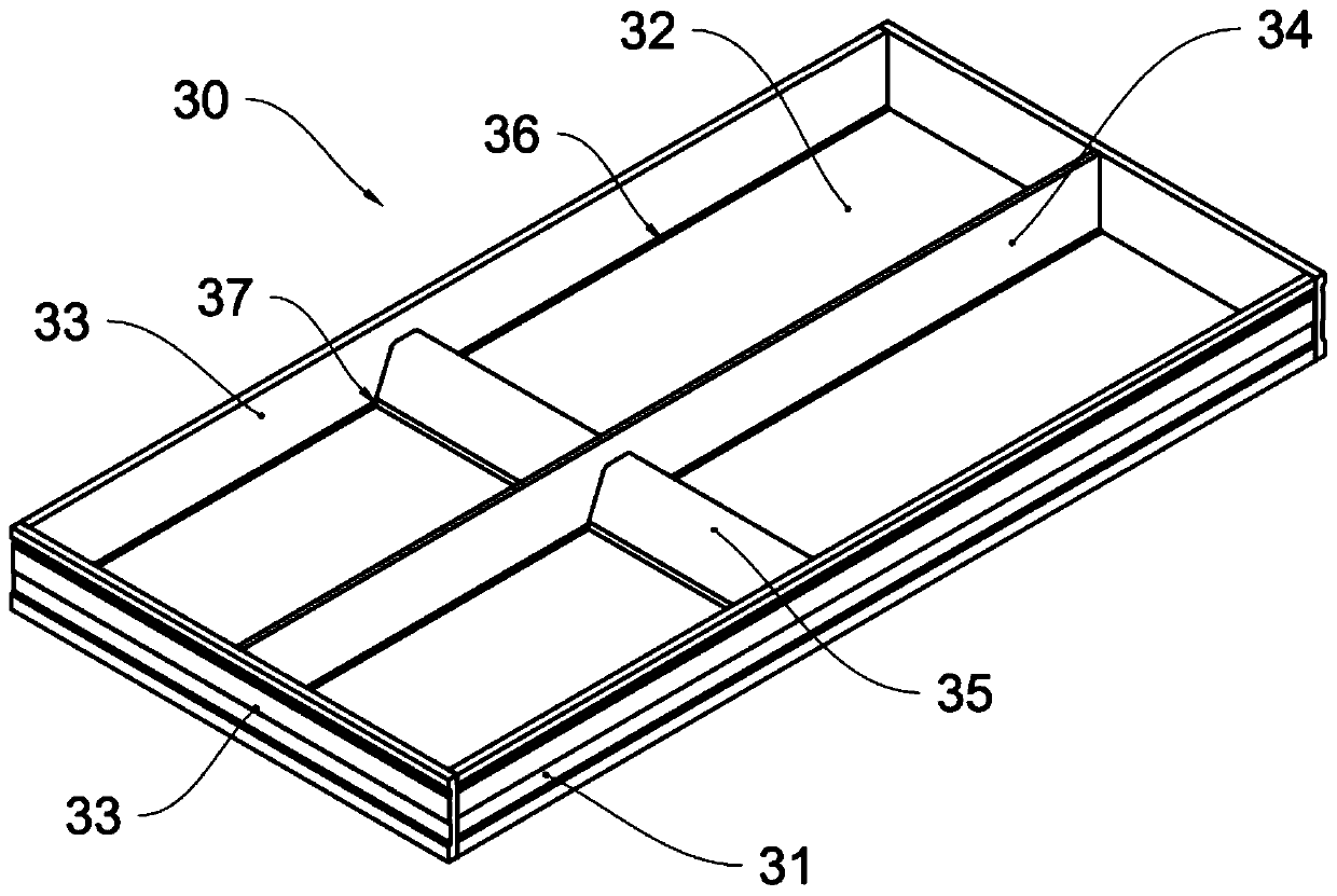
[0036] Realize the welding machine of present embodiment as figure 1 and figure 2 As shown, the welding machine has a base 10 on which a transmission assembly 11 is arranged. In this embodiment, the transmission assembly 11 includes a plurality of cylindrical rollers. Of course, the transmission assembly 11 can also be realized by using a belt or a chain. The aluminum template 30 to be welded may be placed on the transport assembly 11 . Preferably, a motor can be set to drive multiple rollers to rotate, so that the aluminum template to be welded is automatically transferred to the welding station, and is transferred to the unloading station after welding.

[0037] A welding torch 15 as a welding device is arranged above the base 10, and a casing 13 is arranged outside the welding torch 15. Preferably, a part of the casing 13 is made of a transparent material, such as acrylic, to facilitate observation from the outside The case of welding. A color camera 20 is arranged ins...

no. 2 example

[0059] Compared with the first embodiment, this embodiment adopts a depth camera that is a profile scanner, and does not need to use a seam tracker to adjust the motion trajectory of the welding gun. Compared with depth cameras, such as laser structured light cameras, binocular cameras, etc., profile scanners have higher accuracy. Usually, profile scanners calculate the height of the workpiece to be welded by emitting laser light and calculating the return time of the laser light. The profile scanner can be fixed on the base of the welding machine. Of course, the profile scanner can also be fixed on the mechanical arm or the welding gun, and follow the movement of the mechanical arm or the welding gun relative to the base. In this embodiment, since a contour scanner is used, it is not necessary to use a seam tracker to correct the motion trajectory of the welding equipment.

[0060] see Figure 5 After the workpiece to be welded is clamped and fixed, step S11 is performed, an...


PUM


Abstract

The invention provides an automatic identification method for a welding area of a welding workpiece, a computer device and a computer readable storage medium. The method comprises steps that a color image shot by a color camera is obtained, and plane coordinates of a to-be-welded workpiece are calibrated according to the color image; a region of a preset color in the color image is obtained, and the region of the preset color is calibrated as a welding region; a depth image of a to-be-welded workpiece is obtained, and height coordinates of a welding area are calculated; a motion trail of welding equipment is calculated according to the plane coordinates and the height coordinates of the welding area. The invention further provides a computer device and a computer readable storage medium for implementing the method. The method has the advantages that metal templates with different shapes and welding areas can be welded, the method is particularly suitable for production and welding of small-batch multi-variety metal templates, the method is suitable for batch production, and welding precision and efficiency are high.

Description

technical field [0001] The invention relates to the technical field of intelligent manufacturing, in particular to a method for automatically identifying a welding area of ​​a welding workpiece, a computer device and a computer-readable storage medium for realizing the method. Background technique [0002] The construction industry uses a large number of aluminum formwork for building construction. The existing aluminum formwork is usually welded by the bottom plate, multiple side plates, and partitions. If manual welding is used, on the one hand, the welding quality cannot be guaranteed, and on the other hand, due to the low efficiency of manual welding, the production time of the aluminum formwork is long, which affects the processing efficiency of the formwork. Therefore, people consider using automated equipment to weld the aluminum template, for example, using an automated welding machine to weld the aluminum template. [0003] Existing welding machines are all aimed a...

Claims


Application Information

Patent Timeline
Patent Type & Authority Applications(China)
IPC IPC(8): B23K26/03B23K26/22G06K9/00G06T7/00
CPCB23K26/03B23K26/22G06T7/0004G06V20/10
Inventor 曹建华
Owner 珠海屏珠科技有限公司
Why Eureka
Try Eureka