Efficient sweeping mechanism for numerical control machining center

A cleaning mechanism and high-efficiency technology, used in metal processing machinery parts, metal processing equipment, manufacturing tools, etc., can solve the problems of inability to collect and process dust and waste, low cleaning efficiency, low device intelligence, etc., to avoid normal operation. , increase efficiency, high intelligent effect

Inactive Publication Date: 2020-04-07
嘉兴致信精密零部件股份有限公司
View PDF10 Cites 3 Cited by
  • Summary
  • Abstract
  • Description
  • Claims
  • Application Information

AI Technical Summary

Problems solved by technology

[0003] Chinese patent discloses a machining center workpiece cleaning mechanism (authorized notification number CN209175394U). The main shaft of this patented technology is fixed with a cleaning tool handle, and the cleaning tool handle is provided with an air nozzle connected to an air source. However, the above-mentioned device is an air jet Type cleaning, the cleaning efficiency is low, and the wind makes the dust drift inside the CNC machining device, affecting the normal operation of the device, most of the devices cannot quickly collect dust and waste, and most of the collection efficiency is low, and most of the devices are intelligent The conversion is low, and most of the devices cannot be moved left and right on the CNC processing device to clean the inside of the device, and the convenience of use is low

Method used


Image

  • Efficient sweeping mechanism for numerical control machining center
  • Efficient sweeping mechanism for numerical control machining center
  • Efficient sweeping mechanism for numerical control machining center

Examples


Embodiment Construction

[0023] The following will clearly and completely describe the technical solutions in the embodiments of the present invention with reference to the accompanying drawings in the embodiments of the present invention. Obviously, the described embodiments are only some, not all, embodiments of the present invention. Based on the embodiments of the present invention, all other embodiments obtained by persons of ordinary skill in the art without making creative efforts belong to the protection scope of the present invention.

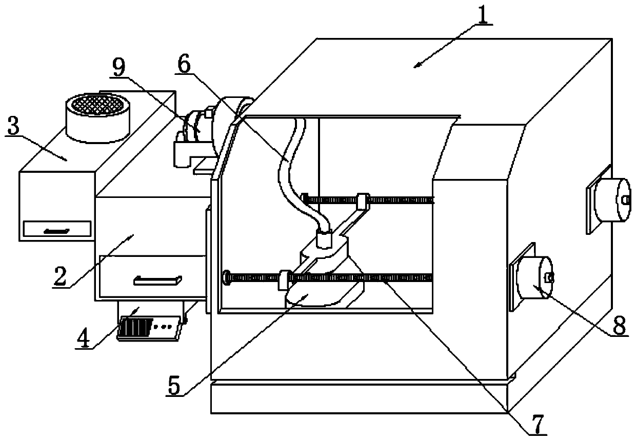
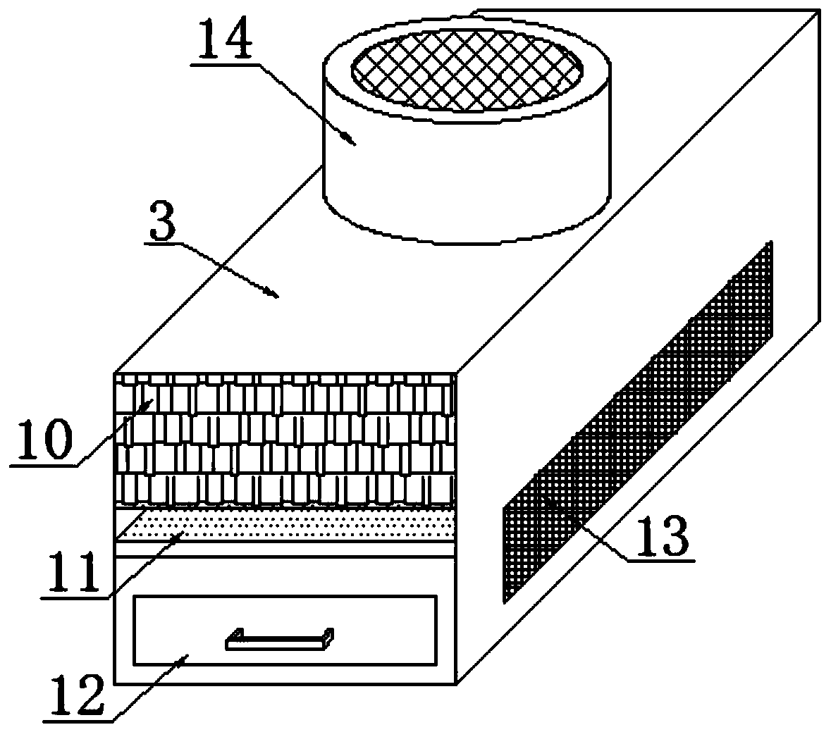
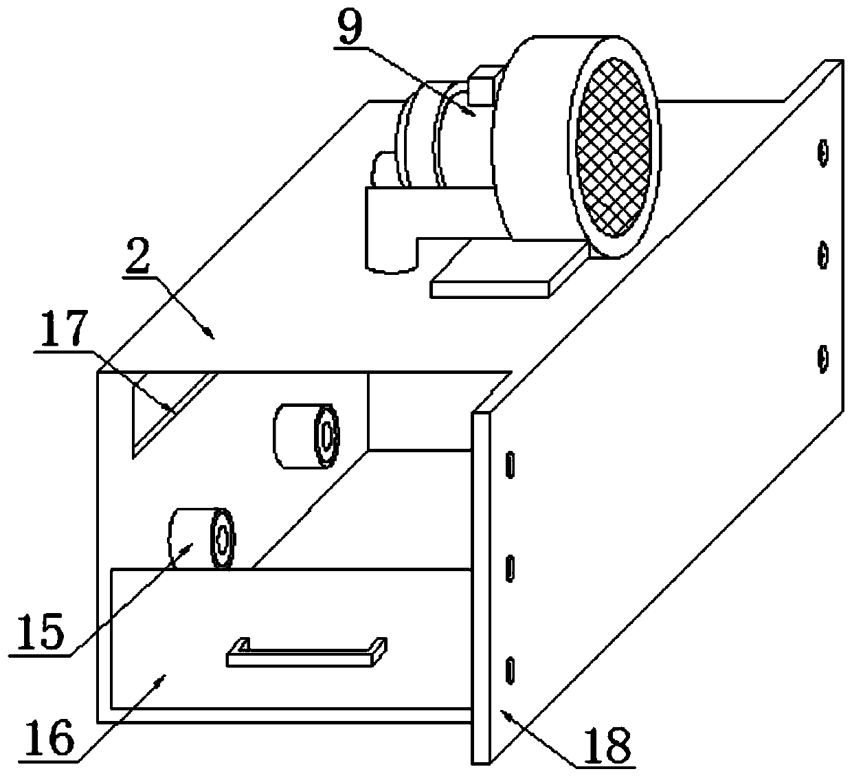
[0024] see Figure 1~5 , in the embodiment of the present invention, a kind of high-efficiency cleaning mechanism that is used for numerical control machining center comprises numerical control machining device 1, and one side of numerical control machining device 1 is equipped with mobile motor 8 (model is 42BYGH series), and one side of mobile motor 8 A threaded rod 7 is welded at a position that runs through one side of the CNC machining device 1, and a cle...


PUM


Abstract

The invention discloses an efficient sweeping mechanism for a numerical control machining center and particularly relates to the technical field of numerical control machining. The mechanism comprisesa numerical control machining device, wherein a moving motor is mounted on one side of the numerical control machining device, a threaded rod is welded to the position, penetrating through one side of the numerical control machining device, of one side of the moving motor, a sweeping mechanism is rotationally mounted on an outer surface of the threaded rod, a scrap pipe is mounted on an upper surface of the sweeping mechanism in a penetrating manner, a first waste scrap collecting box is fixed to an outer surface of one side of the numerical control machining device, a vacuum pump is installed on an upper surface of the first waste scrap collecting box, a second waste scrap collecting box is welded to an upper end of one side of the first waste scrap collecting box in a penetrating mode,and a control box is installed on a lower surface of the first waste scrap collecting box. The mechanism is advantaged in that air suction type sweeping is adopted, sweeping is carried out through a brush, the vacuum pump is arranged, the scrap collecting boxes are provided with electromagnets, independent operation can be carried out, and left-right translation operation can be carried out in thenumerical control machining process.

Description

technical field [0001] The invention relates to the technical field of numerical control machining, in particular to an efficient cleaning mechanism for a numerical control machining center. Background technique [0002] CNC machining refers to a process method for processing parts on CNC machine tools. The process regulations of CNC machine tool processing and traditional machine tool processing are generally consistent, but significant changes have also taken place. Digital information is used to control parts and The mechanical processing method of tool displacement is an effective way to solve the problems of changeable parts, small batches, complex shapes, and high precision and to achieve high-efficiency and automatic processing. The cleaning mechanism removes dust during the work process to avoid affecting the normal operation of the device. . [0003] Chinese patent discloses a machining center workpiece cleaning mechanism (authorized notification number CN209175394...

Claims


Application Information

Patent Timeline
Patent Type & Authority Applications(China)
IPC IPC(8): B23Q11/00
CPCB23Q11/0042B23Q11/0046B23Q11/0064
Inventor 陆志良
Owner 嘉兴致信精密零部件股份有限公司
Why Eureka
Try Eureka