Underwear fabric manufacturing system and method and underwear fabric

A technology of underwear fabric and manufacturing system, which is applied in the cutting of underwear, textiles, papermaking, and textile materials. It can solve the problems of automatic processing of underwear and achieve good cutting effect and uniform force.

Active Publication Date: 2020-04-07
江苏虞美人纺织品有限公司
View PDF10 Cites 3 Cited by
  • Summary
  • Abstract
  • Description
  • Claims
  • Application Information

AI Technical Summary

Problems solved by technology

However, this device cannot automatically process the underwear so that it can be cut to the desired shape

Method used


Image

  • Underwear fabric manufacturing system and method and underwear fabric
  • Underwear fabric manufacturing system and method and underwear fabric
  • Underwear fabric manufacturing system and method and underwear fabric

Examples


specific Embodiment approach 1

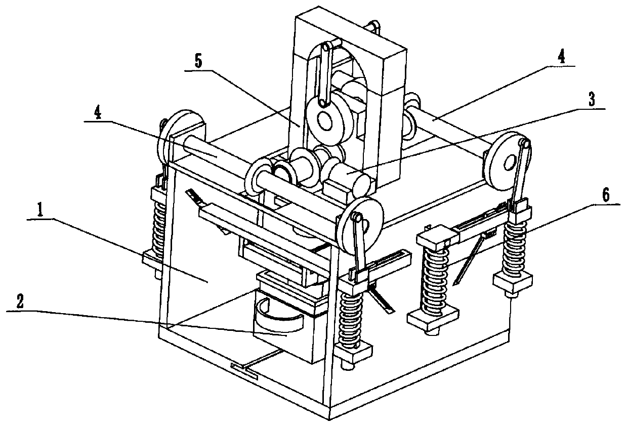
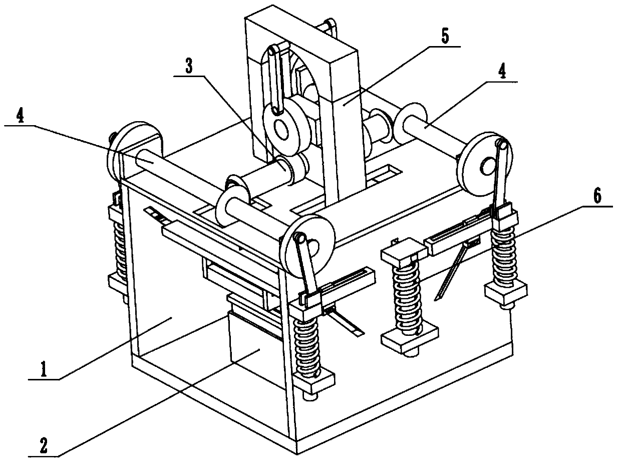
[0034] Such as Figure 1 to Figure 11 As shown, a kind of underwear fabric manufacturing system includes a fixed cutting base 1, a receiving combined cutting base 2, a drive connector 3, two inclined driving extrusion fixers 4, an upper connection driver 5 and a combined cutter 6, the described The receiving combined cutting base 2 is slidably connected in the fixed cutting base 1, and the driving connector 3 is fixedly connected to the upper end of the fixed cutting base 1, and the two ends of the driving connector 3 are respectively meshed with transmission and connected to two inclined driving extrusion holders 4, the two A tilt-driven extruding fixer 4 and combined cutter 6 are all slidably connected to the fixed cutting base 1, the upper connection driver 5 is hinged on the drive connector 3, and the combined cutter 6 is fixedly connected to the lower end of the upper connection driver 5, combined The lower end of cutter 6 fits with receiving combination cutting seat 2. ...

specific Embodiment approach 2

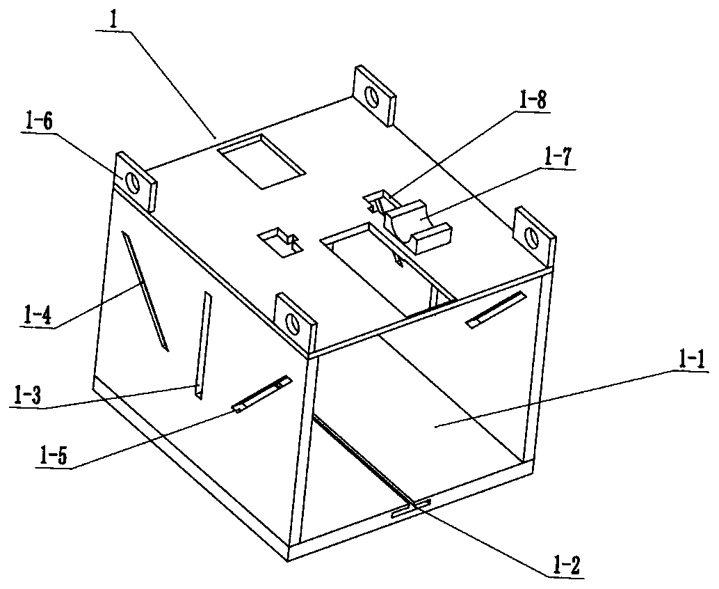
[0036] Such as Figure 1 to Figure 11 As shown, this embodiment will further describe Embodiment 1. The fixed cutting base 1 includes an operating frame 1-1, a T-shaped sliding groove 1-2, two vertical sliding grooves 1-3, and two rear inclined sliding grooves. 1-4, two front inclined sliding grooves 1-5, four rotating seats 1-6, motor fixing seats 1-7 and two limit slider grooves 1-8, set on the lower side of the inner wall of the operating frame 1-1 There are T-shaped sliding grooves 1-2, two vertical sliding grooves 1-3 run through the center of the two ends of the operation frame 1-1 respectively, and two rear inclined sliding grooves 1-4 run through the centers of the two ends of the operation frame 1-1 respectively. On the rear side, two front inclined sliding grooves 1-5 are respectively set on the front side of the two ends of the operation frame 1-1, and the four rotating seats 1-6 are evenly and fixedly connected to the upper end of the operation frame 1-1, and the m...

specific Embodiment approach 3

[0038] Such as Figure 1 to Figure 11 As shown, this embodiment further explains the second embodiment, the receiving combined cutting seat 2 includes a load recovery frame 2-1, a T-shaped sliding block 2-2, a handle ring 2-3, and a forming matching bottom sleeve 2-4. The left extruded and fixed U-shaped groove 2-5 and the right and left extruded and fixed U-shaped groove 2-6 are fixedly connected with the lower end of the load recovery frame 2-1 to the T-shaped sliding block 2-2, which is the load recovery frame 2 -1 is slidably connected in the T-shaped sliding groove 1-2 through the T-shaped sliding block 2-2, the handle ring 2-3 is fixedly connected to the load recovery frame 2-1, and the forming matching bottom sleeve 2-4 is fixedly connected to the In the load recovery frame 2-1, the left extrusion fixed U-shaped groove 2-5 and the right left extrusion fixed U-shaped groove 2-6 are respectively arranged on the upper sides of the load recovery frame 2-1 two ends. When it...


PUM


Abstract

The invention belongs to the underwear fabric processing field, and more specifically relates to an underwear fabric manufacturing system and method and an underwear fabric. The processing method comprises the following steps of enabling a receiving combined cutting base to slide to a specified position in a fixed cutting base, and enabling the cloth to intermittently pass between the receiving combined cutting base and a combined cropper, wherein the receiving combined cutting base, a drive connector, two tilt drive extrusion fixers, an upper connection driver and a combined cropper are included; connecting the drive connector to a power supply to drive the two tilt drive extrusion fixers to rotate, so that the two tilt drive extrusion fixers synchronously reciprocate on the fixed cuttingbase, thus the intermittently passing cloth is extruded at the two ends of the receiving combined cutting base, and clamping and fixing the stopped cloth; and driving the fixed cutting base on the upper connection driver and the combined cropper to vertically reciprocate. According to the underwear fabric processed by the method, the compositions of the fabric are 30% cotton, 30% silk and 40% chemical fiber.

Description

technical field [0001] The invention relates to the field of underwear fabric processing, and more specifically relates to an underwear fabric manufacturing system. Background technique [0002] Patent No. CN201720756369.4 discloses an underwear processing equipment, including: a support frame; a workbench fixed on the support frame; a processing unit fixed on the workbench; on the support frame, located below the workbench, to provide power for the processing unit; the operation box is fixedly arranged on the support frame, located below the workbench, and electrically connected to the motor unit; A protective frame is fixedly arranged on at least three sides of the workbench, and the protective frame protrudes upward from the plane of the workbench. The protective frame of the utility model can make the equipment more effectively prevent the underwear on the workbench and the processing tools used for processing from falling to the ground, avoiding the situation that the ...

Claims


Application Information

Patent Timeline
Patent Type & Authority Applications(China)
IPC IPC(8): D06H7/00A41B17/00
CPCA41B17/00D06H7/00
Inventor 延相东
Owner 江苏虞美人纺织品有限公司
Why Eureka
Try Eureka