Electric pile gas-liquid distribution device and fuel cell applying same

A gas-liquid distribution and distribution device technology, applied in fuel cells, fuel cell additives, electrical components, etc., can solve problems such as single function

Pending Publication Date: 2020-04-07
ZHONGSHAN BROAD OCEAN
View PDF8 Cites 2 Cited by
  • Summary
  • Abstract
  • Description
  • Claims
  • Application Information

AI Technical Summary

Problems solved by technology

[0004] The purpose of the present invention is to provide a gas-liquid distribution device for electric stacks and a fuel cell for

Method used


Image

  • Electric pile gas-liquid distribution device and fuel cell applying same
  • Electric pile gas-liquid distribution device and fuel cell applying same
  • Electric pile gas-liquid distribution device and fuel cell applying same

Examples


Embodiment 1

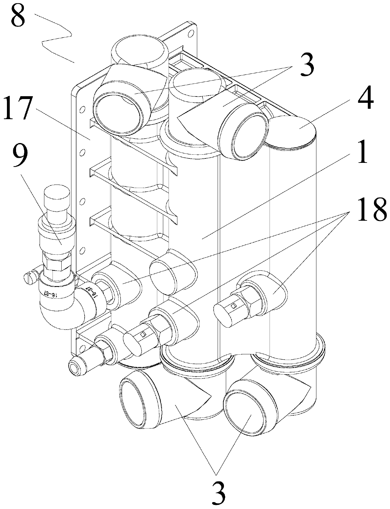
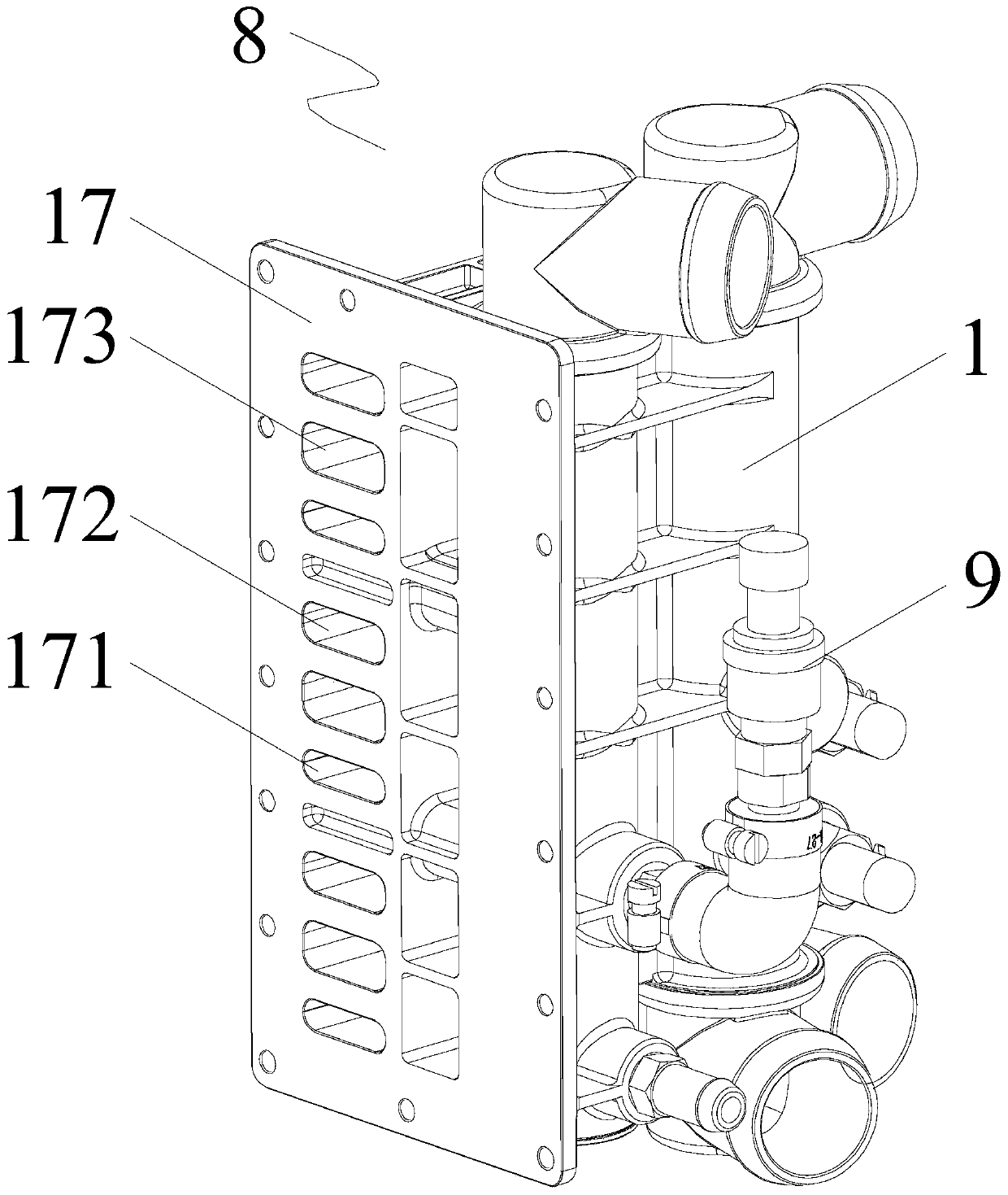
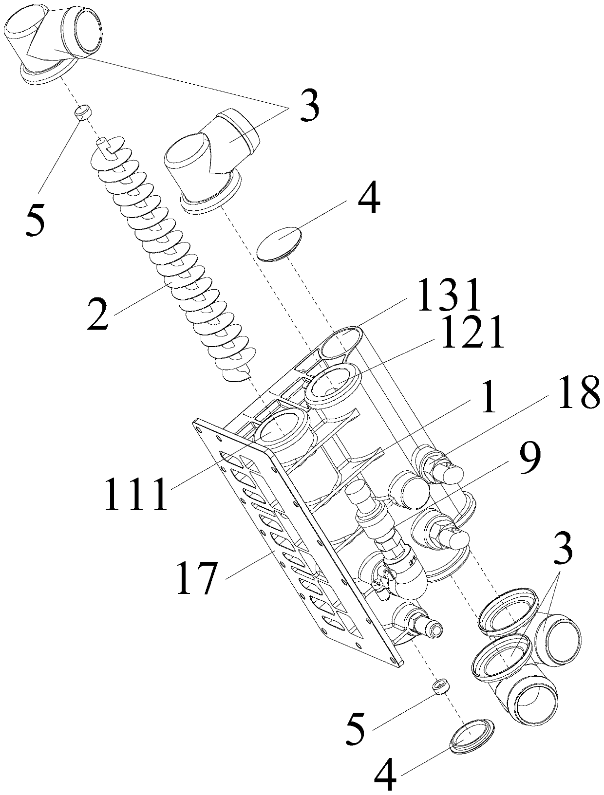
[0032] Such as Figure 1 to Figure 10 As shown, what this embodiment provides is a stack gas-liquid distribution device, including a block main body 1, and the main block body 1 is provided with a hydrogen main channel 11 for hydrogen circulation, an air main channel 12 for air circulation, and The cooling liquid main channel 13 for cooling liquid circulation, the hydrogen main channel 11, the air main channel 12 and the cooling liquid main channel 13 are vertically facing and separated from each other, a gas-liquid separation device is installed in the hydrogen main channel 11, and the gas-liquid separation device It is the spiral reamer blade 2. After the moist hydrogen gas mixture enters the main hydrogen channel 11, it will flow upwards in a spiral shape along the helical reamer blade 2 to form an outer swirling air flow; the outer swirling air flow will generate centrifugal force during the rotation process, and the hydrogen in the outer swirling air flow will rotate and ...

Embodiment 2

[0041] Such as Figure 11As shown, what this embodiment provides is a fuel cell, including a stack module 6, an input stack gas-liquid distribution device 7 and an output stack distribution device 8, and the stack module 6 is composed of several fuel cell units 60 are stacked from bottom to top, and one side of each fuel cell unit 60 is provided with a hydrogen input port, an air input port and a cooling liquid input port, and the hydrogen gas input port, the air input port and the cooling liquid input port The outlets are distributed from top to bottom, and the other side is provided with hydrogen outlets, air outlets and coolant outlets, the hydrogen outlets, air outlets and coolant outlets are respectively distributed from top to bottom, so The hydrogen input port, the air input port and the cooling liquid input port are connected to the input stack gas-liquid distribution device 7, and the hydrogen output port, the air output port and the cooling liquid output port are con...


PUM


Abstract

The invention discloses an electric pile gas-liquid distribution device and a fuel cell applying the same. The device comprises a collecting block body, and the collecting block body is provided witha hydrogen main flow channel for hydrogen to circulate, an air main flow channel for air to circulate and a cooling liquid main flow channel for cooling liquid to circulate; the hydrogen main flow channel, the air main flow channel and the cooling liquid main flow channel face vertically and are separated from one another, and spiral auger blades are installed in the hydrogen main flow channel. After entering the hydrogen main flow channel, the humid hydrogen mixed gas spirally flows upwards along the spiral auger blades to form an outer spiral gas flow; a centrifugal force can be generated inthe rotating process of the external rotating airflow; hydrogen in the external rotation gas flow rotationally rises to an elbow at the top of the hydrogen main flow channel, liquid drops with high density in the external rotation gas flow are thrown to the wall surface of the hydrogen main flow channel, lose inertia force after being in contact with the wall surface, fall along the wall surfaceby virtue of the momentum of inlet speed and downward gravity, and enter the bottom, so the effect of water-vapor separation is achieved.

Description

Technical field: [0001] The invention relates to an electric stack gas-liquid distribution device and a fuel cell applied thereto. Background technique: [0002] The fuel cell system is mainly divided into two assemblies: the fuel cell module assembly and the air compressor assembly. The air compressor assembly includes an air compressor, an air mass flow meter, an air filter, a temperature sensor and related brackets and pipelines, and its main function is to provide the fuel cell module with compressed air that meets the requirements. The fuel cell module assembly includes water pumps, water pump controllers, thermostat valves, heaters, intercoolers, humidifiers and related brackets and pipelines, hydrogen supply and return hydrogen injector devices, stacks, clusters, and electrical controls Components, boxes and related pipelines, etc. [0003] The gas at the outlet of the hydrogen gas path of the existing hydrogen fuel cell stack is a mixed gas of a large amount of wat...

Claims


Application Information

Patent Timeline
IPC IPC(8): H01M8/04029H01M8/04082H01M8/04089H01M8/04119H01M8/2457
CPCH01M8/04089H01M8/04201H01M8/04164H01M8/04029H01M8/2457Y02E60/50
Inventor 李勇邓佳梁未栋韦庆省王宏旭易勇毛锋锋赵勇富刘小青
Owner ZHONGSHAN BROAD OCEAN
Why Eureka
Try Eureka