Check patentability & draft patents in minutes with Patsnap Eureka AI!

Combined high-temperature compression clamp

A high-temperature compression and combined technology, which is applied in the direction of manufacturing tools, workpiece clamping devices, etc., can solve problems such as inability to meet the compression strength test, and achieve the effects of compact structure, low production cost, stability and uniformity

Active Publication Date: 2020-04-10
AEROSPACE INST OF ADVANCED MATERIALS & PROCESSING TECH
View PDF5 Cites 0 Cited by
  • Summary
  • Abstract
  • Description
  • Claims
  • Application Information

AI Technical Summary

Problems solved by technology

However, none of the high-temperature compression fixtures that have been publicly reported can meet the compressive strength test of short-column specimens with a load of 100kN or more in a radiation-heated vacuum / inert atmosphere high-temperature furnace above 2500°C.

Method used


Image

  • Combined high-temperature compression clamp
  • Combined high-temperature compression clamp
  • Combined high-temperature compression clamp

Examples


Embodiment Construction

[0025] In order to make the purpose, technical solutions and advantages of the present invention clearer, the technical solutions of the present invention will be clearly and completely described below in conjunction with the accompanying drawings in the embodiments of the present invention. Obviously, the described embodiments are the embodiment of the present invention. Some examples, but not all examples. Based on the embodiments of the present invention, all other embodiments obtained by persons of ordinary skill in the art without making creative efforts belong to the protection scope of the present invention.

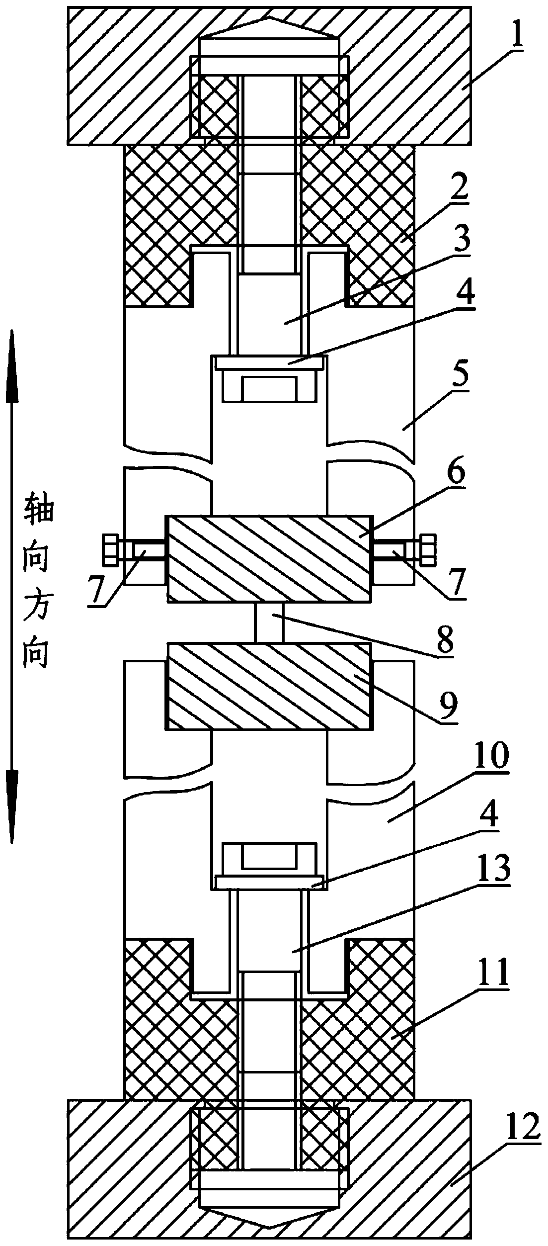
[0026] The invention provides a combined high-temperature compression fixture, which can be applied to the compression strength test of a short-column sample with a load of more than 100kN in a radiation-heated vacuum / inert atmosphere high-temperature furnace above 2500°C. figure 1 It is a structural schematic diagram of a high-temperature compression fixture in a...


PUM


Abstract

The invention relates to a combined high-temperature compression clamp. An upper compression clamp and a lower compression clamp are included and symmetrically arranged. From top to bottom, the uppercompression clamp comprises an upper connecting rod, an upper pressing rod and an upper pressing head which are sequentially coaxially connected, and a through hole for a first connecting screw to penetrate is formed in the upper connecting rod and the upper pressing rod, wherein the upper connecting rod and the upper pressing rod are connected through the first connecting screw. From bottom to top, the lower compression clamp comprises a lower connecting rod, a lower pressing rod and a lower pressing head which are sequentially coaxially connected, and a through hole for a second connecting screw to penetrate is formed in the lower connecting rod and the lower pressing rod, wherein the lower connecting rod and the lower pressing rod are connected through the second connecting screw. The upper pressing head and the lower pressing head are used for clamping a to-be-tested sample. The upper connecting rod, the lower connecting rod, the first connecting screw and the second connecting screw are made of metal materials, and the upper pressing rod, the lower pressing rod, the upper pressing head and the lower pressing head are made of carbon-carbon or carbon-ceramic materials. Accordingto the combined high-temperature compression clamp, rigidity connection between the pressing rods and the connecting rods is achieved through a compact structure, and the combined high-temperature compression clamp is conveniently installed in a radiation heating vacuum / inertia atmosphere high-temperature furnace at 2,500 DEG C or above and can be used for compression strength testing of short-column samples with the load being 100kN or above.

Description

technical field [0001] The invention belongs to the technical field of high-temperature testing of experimental mechanics, and in particular relates to a combined high-temperature compression fixture. Background technique [0002] With the development of hypersonic aircraft, the extreme environment in its service state puts forward higher requirements on the high temperature resistance of materials, and its local parts need to withstand high temperatures above 2500 ° C. Therefore, it is urgent to develop new high temperature resistant materials. New materials such as fiber-reinforced ceramic matrix composites, ultra-high temperature ceramics and refractory metals have been developed. The development, testing and application of these materials all rely on accurate and complete data on high-temperature mechanical properties of materials, among which high-temperature compressive strength is one of the most basic and important performance parameters of such high-temperature-resi...

Claims


Application Information

Patent Timeline
IPC IPC(8): B25B11/00
CPCB25B11/00
Inventor 周志亮周金帅王华琼高增华李想苏江张昊
Owner AEROSPACE INST OF ADVANCED MATERIALS & PROCESSING TECH
Features
  • R&D
  • Intellectual Property
  • Life Sciences
  • Materials
  • Tech Scout
  • Unparalleled Data Quality
  • Higher Quality Content
  • 60% Fewer Hallucinations
Learn More