Fireproof isolation bandage
A fireproof isolation and strapping technology, which is applied in the direction of cable installation devices, electrical components, layered products, etc., can solve the problems of reducing the protection efficiency of the strapping, and the cable strapping is not fireproof, and achieves good heat insulation and fire prevention effects and simple construction Effect
- Summary
- Abstract
- Description
- Claims
- Application Information
AI Technical Summary
Problems solved by technology
Method used
Image
Examples
Embodiment 1
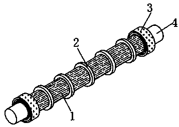
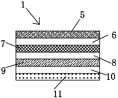
[0033] see Figure 1-2 , a fireproof isolation strap, including a strap body 1, the strap body 1 is wound and arranged on the surface of the cable 4; both ends of the strap body 1 are fixedly connected with three layers of reinforcement patches 3, and the surface of the strap body 1 is equidistantly fixedly connected with five Self-locking stainless steel cable tie 2, the strap body 1 is a flexible fire-resistant strap, and the reinforcement patch 3 is a 75°C irreversible temperature-measuring patch; the outer side of the flexible fire-resistant strap is fixedly connected with 1MM Kevlar bulletproof fiber cloth 11; flexible and fire-resistant From the inside to the outside, the straps are glass fiber decorative cloth A5, aluminum silicate fireproof cloth A6, aluminum silicate fiber blanket 7, aluminum silicate fireproof cloth B8, glass fiber decorative cloth B9 and high-viscosity and high-temperature resistant acrylic acid glue 10 , high-viscosity and high-temperature-resistan...
Embodiment 2
[0036] see Figure 3-4 , based on Embodiment 1, the difference is that;
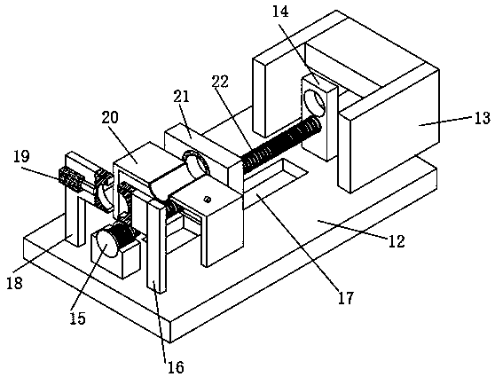
[0037] The strap body 1 is equipped with a winding device. The winding device includes a fixed plate 12, a wire inlet mechanism 13 and a drive motor 15. The wire inlet mechanism 13 and the drive motor 15 are respectively fixedly connected to the two ends of the fixed plate 12; the center of the upper wall of the fixed plate 12 A slide rail 17 is provided, and a winding mechanism 21 is slidably connected in the slide rail 17; a fixed frame A16 and a fixed frame B18 are respectively fixedly connected to the two sides of the drive motor 15, and the fixed frame A16 and the fixed frame B18 are fixed to the winding mechanism 21. Connect the limit frame 20, and the upper wall of the limit frame 20 is fixedly connected with a strap fixing clip 23;
[0038] The drive motor 15 is fixedly connected with a transmission screw 22 through the output shaft, the transmission screw 22 runs through the winding mechanism 2...
Embodiment 3
[0042] see Figure 5-6 , based on Embodiment 1 and 2, the difference is that;
[0043] The wire feeding mechanism 13 includes a wire feeding wheel A26 and a wire feeding wheel B27, the wire feeding wheel A26 and the wire feeding wheel B27 are meshed and connected, and the center of the wire feeding wheel A26 and the wire feeding wheel B27 is fixedly connected with a rubber ring 28; the central shaft of the wire feeding wheel A26 It is fixedly connected with the output shaft of the incoming line motor 25, and the incoming line motor 25 is fixedly connected with the side wall of the mounting plate of the incoming line mechanism 13;
[0044] One side of the wire inlet wheel B27 is fixedly connected with a fixed block A29, and the inner walls of the two side plates of the wire inlet mechanism 13 are correspondingly fixedly connected with a fixed block B30, and the fixed block A29 and the fixed block B30 on the same side correspond to the fixed block B30 on the other side Connecto...
PUM
 Abstract
Description
Claims
Application Information
 - R&D
- Intellectual Property
- Life Sciences
- Materials
- Tech Scout
- Unparalleled Data Quality
- Higher Quality Content
- 60% Fewer Hallucinations
Browse by: Latest US Patents, China's latest patents, Technical Efficacy Thesaurus, Application Domain, Technology Topic, Popular Technical Reports.
© 2025 PatSnap. All rights reserved.Legal|Privacy policy|Modern Slavery Act Transparency Statement|Sitemap|About US| Contact US: help@patsnap.com


