Rotor system and micro gas turbine generator set

A rotor and compressor technology, applied in gas turbine installations, machines/engines, mechanical equipment, etc., can solve the problems of poor rotor system stability, coaxiality deviation, coupling damage, etc., and achieve good stability and high verticality. , the effect of long life

Pending Publication Date: 2020-04-10
TECH XANADU OF RESONATORY SOLAR SYSTD CO LTD +1
View PDF0 Cites 1 Cited by
  • Summary
  • Abstract
  • Description
  • Claims
  • Application Information

AI Technical Summary

Problems solved by technology

[0004] In the prior art, a coupling is usually used to connect the gas turbine rotor and the generator rotor, and the stability of the rotor system is poor due to the deviation of the coaxiality
At the same time, the setting of the coupling restricts the setting position of the thrust bearing. This is because as the rotor speed increases, the axial force on the rotor will further increase. If the thrust bearing is set between the compressor and the turbine, it will The center of gravity of the entire rotor system is biased toward the turbine side, resulting in poor stability of the rotor system
If the thrust bearing is placed on the side of the coupling facing the generator, all the axial force of the rotor will act on the coupling, which will easily cause damage to the coupling

Method used


Image

  • Rotor system and micro gas turbine generator set
  • Rotor system and micro gas turbine generator set
  • Rotor system and micro gas turbine generator set

Examples


Embodiment 1

[0066] In this embodiment, a motor structure is provided in which the stator winding is wound in a back-winding manner.

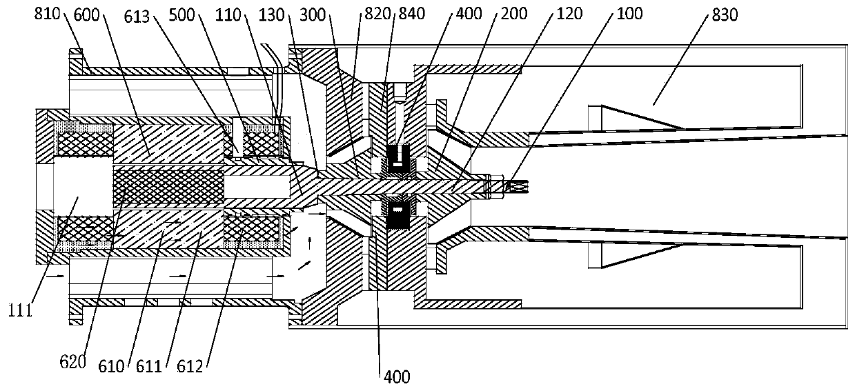
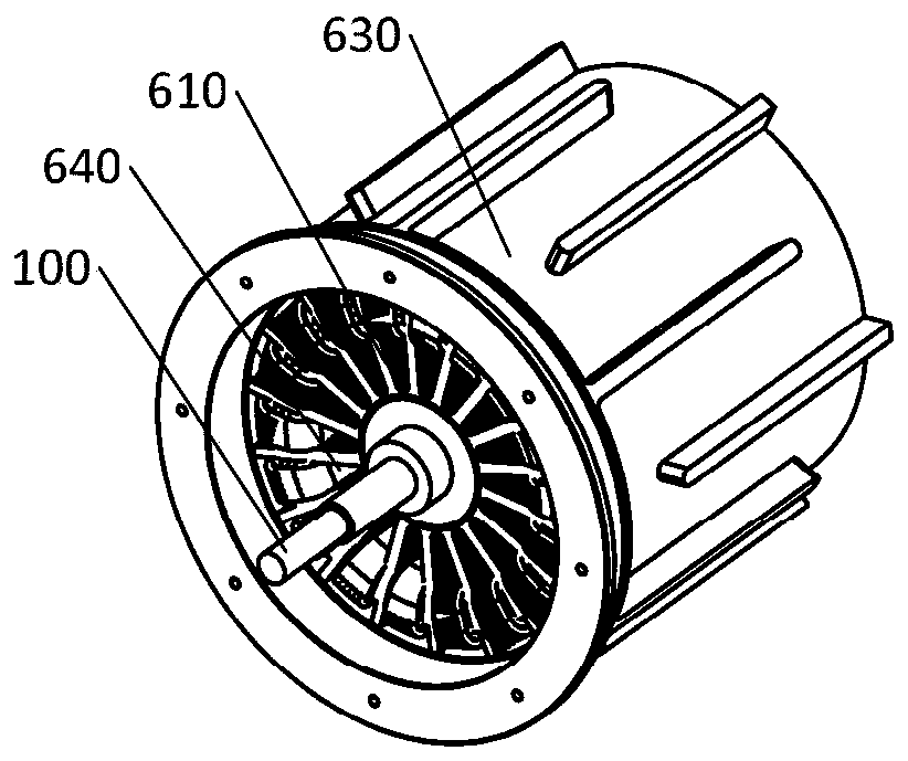
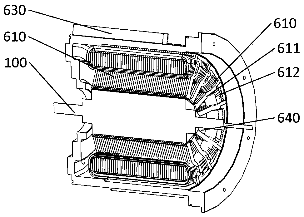
[0067] Specifically, such as figure 2 As shown, the motor 600 includes: a motor stator 610, a motor rotor 620 (not shown in this figure), and a motor housing 630. The motor stator 620 is sleeved on the rotating shaft 100 and maintains a certain gap with the rotating shaft 100 in the radial direction. The motor housing 630 is disposed on the outer periphery of the motor stator 410 , and the motor stator 610 is provided with a plurality of air inlets 640 axially penetrating through the motor stator 610 .

[0068] Since the air inlet 640 is provided, the air intake of the compressor 300 can enter the compressor 300 through the air inlet 640, so that the air intake of the compressor 300 is more sufficient, and at the same time, the normal temperature air passing through the air inlet 640 can It also plays a certain role in cooling the motor stator 610.

[00...

Embodiment 2

[0079] In this embodiment, a structure of an integrated bearing 400 is provided. The integrated bearing 400 includes a radial bearing part and a thrust bearing part. The radial bearing part and the thrust bearing part are integrally formed or finished after assembly. Therefore, the radial bearing part The verticality between the central axis of the rotor and the thrust surface of the thrust bearing is high, the rotor system is installed with high precision and runs smoothly.

[0080] Specifically, see Figure 7 , one-piece bearing 400 includes:

[0081] The first thrust plate 410 and the second thrust plate 420 are fixedly installed on the second shaft segment 120, the first thrust plate 410 and the second thrust plate 420 are arranged oppositely, and an annular groove 430 is formed between them;

[0082] The bearing stator 440 is installed in the annular groove 430 and connected with the rotor system housing 450, and there is a first axial clearance between the two end faces...

Embodiment 3

[0102] In this embodiment, an anti-rotation structure for the one-piece bearing 400 in the second embodiment is provided. The bearing stator 440 of the integrated bearing 400 is installed in the rotor system housing 450 and the rotor system end cover 460, the rotor system housing 450 is sleeved on the circumference of the bearing stator 440 and one end surface, and the rotor system end cover 460 is sleeved on the rotating shaft 100 and located on the other end surface of the bearing stator 440 to realize the axial limit of the other side of the bearing stator 440. An anti-rotation member is arranged between the rotor system housing 450 and the bearing stator 440, and the anti-rotation member is used to realize the circumferential positioning of the bearing stator 440 relative to the rotor system housing 450, so as to prevent the bearing stator 440 from moving with the first thrust plate 410 or the second thrust plate 410. Thrust plate 420 rotates.

[0103] Specifically, one e...


PUM


Abstract

The invention provides a rotor system and a micro gas turbine generator set. The rotor system involves a rotating shaft, a motor, a radial bearing, an air compressor, an integrated bearing and a turbine, wherein the rotating shaft is of an integrated structure, and the motor, the radial bearing, the air compressor, the integrated bearing and the turbine are sequentially arranged on the rotating shaft; and the motor comprises a motor stator and a rotor iron core, wherein the motor stator sleeves one end of the rotating shaft, a motor rotor iron core mounting cavity is formed in the end, sleevedwith the motor stator, of the rotating shaft, a rotor iron core is arranged in the motor rotor iron core mounting cavity, and the port of the motor rotor iron core mounting cavity is not closed. According to the rotor system and the generator set, the layout of the rotor system is compact, the axial size of the rotor system is short, the stability of the high-speed operation is good, the rotatingshaft is of an open structure, the heat dissipation performance of the motor rotor core is good, the rotating shaft is not prone to be deformed and the precision is high.

Description

technical field [0001] The invention relates to the technical field of rotor dynamics, in particular to a rotor system and a micro gas turbine generating set. Background technique [0002] The micro gas turbine is a newly developed small heat engine, its stand-alone power ranges from 25 to 300kW, and its basic technical features are radial flow impeller machinery and regenerative cycle. A micro gas turbine mainly includes three major components: a compressor, a combustor and a turbine. After entering the compressor, the air is compressed into high-temperature and high-pressure air, which is then supplied to the combustion chamber for mixed combustion with fuel, and the high-temperature and high-pressure gas generated expands in the turbine to perform work. When the rotor rotates at high speed, the rotor will be subjected to radial force and axial force. In order to limit the radial and axial movement of the rotating shaft, radial bearings and thrust bearings need to be ins...

Claims


Application Information

Patent Timeline
Patent Type & Authority Applications(China)
IPC IPC(8): F02C3/04F02C7/06
CPCF02C3/04F02C7/06
Inventor 靳普刘慕华
Owner TECH XANADU OF RESONATORY SOLAR SYSTD CO LTD
Why Eureka
Try Eureka