Hydraulic pump and sprayer based open type isothermal compressed air energy storage system and method

A compressed air energy storage, compressed air technology, applied in the direction of pressure pumps, liquid variable capacity machinery, pumps, etc., can solve the problems of volume energy storage density reduction, system volume occupation, system volume increase, etc., to achieve volume energy storage density The effect of increasing and improving energy storage efficiency and reducing compression power consumption

Active Publication Date: 2020-04-10
ZHENGZHOU UNIVERSITY OF LIGHT INDUSTRY
View PDF5 Cites 3 Cited by
  • Summary
  • Abstract
  • Description
  • Claims
  • Application Information

AI Technical Summary

Problems solved by technology

However, the traditional isothermal compressed air energy storage system is a closed system that requires two working fluids, air is the energy storage working fluid and liquid is the power generation working fluid, both of which need to occupy the system volume
Therefore, compared with a non-isothermal compressed air energy storage system with a single working fluid, its system volume is doubled, resulting in a reduction of its volumetric energy storage density to 50%.
In addition, in the actual isothermal compressed air energy storage system, due to the limitation of the gas-liquid contact heat transfer area, the actual temperature change during the compression and expansion process is still large, resulting in the actual cycle efficiency being much lower than the ideal cycle.

Method used


Image

  • Hydraulic pump and sprayer based open type isothermal compressed air energy storage system and method
  • Hydraulic pump and sprayer based open type isothermal compressed air energy storage system and method
  • Hydraulic pump and sprayer based open type isothermal compressed air energy storage system and method

Examples


Embodiment Construction

[0048] The following will clearly and completely describe the technical solutions in the embodiments of the present invention with reference to the accompanying drawings in the embodiments of the present invention. Obviously, the described embodiments are only some, not all, embodiments of the present invention. Based on the embodiments of the present invention, all other embodiments obtained by persons of ordinary skill in the art without making creative efforts belong to the protection scope of the present invention.

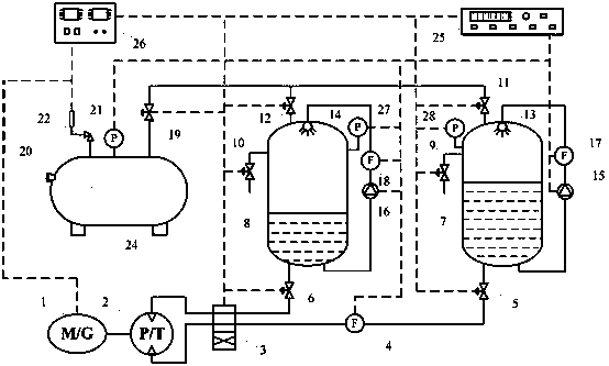
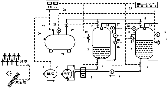
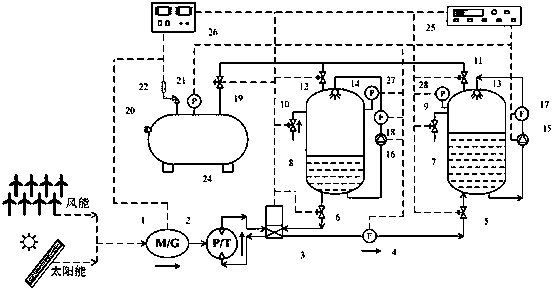
[0049] Such as figure 1 As shown, an open isothermal compressed air energy storage system based on hydraulic pumps and sprayers can be applied to power system peak shifting and valley filling, and can also be applied to storage and large-scale Grid-connected, including motor / generator 1, hydraulic pump / turbine 2, first working chamber 8 for compressed air, second working chamber 7, high-pressure gas storage tank 20, data acquisition unit 25 and control unit 26...


PUM


Abstract

The invention discloses a hydraulic pump and sprayer based open type isothermal compressed air energy storage system and method. The system comprises an electric machine/power generator which is connected with a hydraulic pump/turbine, wherein the hydraulic pump/turbine communicates with a reversing valve; the reversing valve separately communicates with a first working cavity and a second workingcavity through a first valve group; the first working cavity and the second working cavity separately communicate with a high-pressure gas storage tank through a second valve group; pressure monitoring devices are arranged on the first working cavity, the second working cavity and the high-pressure gas storage tank; and a spraying mechanism and a third valve group are arranged on the first working cavity and the second working cavity. The hydraulic pump and sprayer based open type isothermal compressed air energy storage system adopts the hydraulic pump and the sprayer to realize isothermal compression/expansion, so that compression work is reduced, expansion work is improved, and energy storage efficiency and energy utilization efficiency of the system are improved; and the reversing valve is adopted, so that two working cavities alternatively work, and therefore, a compression/expansion time ratio of the system is increased, continuous energy storage/release is realized, and systemcapacity and manufacturing cost are reduced.

Description

technical field [0001] The invention relates to the technical field of compressed air energy storage, in particular to an open isothermal compressed air energy storage system based on a hydraulic pump and a sprayer and a working method. Background technique [0002] Compressed air energy storage technology has great potential in large-scale grid connection of intermittent renewable energy, peak load regulation of power system, and reduction of carbon emissions. Large size, high conversion efficiency, high reliability, economic feasibility, and small construction constraints. [0003] The basic principle of compressed air energy storage is: use low-peak electricity, wind power, photoelectricity, etc. to drive compressors to compress the air, and store electric energy in the form of air pressure energy in underground mines or high-pressure gas storage tanks; , the stored compressed air expands to do work, driving the turbine to generate electricity. According to the way of h...

Claims


Application Information

Patent Timeline
Patent Type & Authority Applications(China)
IPC IPC(8): F04B41/02F04B41/06F04F13/00F04B39/10F04B39/06F04D13/06F03B13/00F03B3/10F04F1/10F04B49/06F04B49/22F03B15/00
CPCF03B3/103F03B13/00F03B15/00F04B39/062F04B39/10F04B41/02F04B41/06F04B49/06F04B49/22F04D13/06F04F1/10F04F13/00Y02E10/20Y02E60/16
Inventor 陈华彭钰航
Owner ZHENGZHOU UNIVERSITY OF LIGHT INDUSTRY
Why Eureka
Try Eureka